
A comparator is an electronic component that compares two input voltages. Comparators are closely related to operational amplifiers, but a comparator is designed to operate with positive feedback and with its output saturated at one power rail or the other. If necessary, an op-amp can be pressed into service as a poorly performing comparator, but its slew Rate will be impaired.
Comparator

Bistable output that indicates which of the two inputs has a higher voltage. That is,

where and are nominally the positive and negative supply voltages (which are not shown in the diagram).


Threshold detector

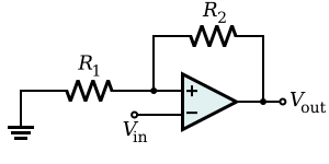
The threshold detector with hysteresis consists of an operational amplifier and a series of resistors that provide hysteresis.[1]: 5 [2]: 7 [3] Like other detectors, this device functions as a voltage switch, but with an important difference. The state of the detector output is not directly affected by input voltage, but instead by the voltage drop across its input terminals (here, referred to as Va). From Kirchhoff's Current Law, this value depends on Vin and the output voltage of the threshold detector itself, both multiplied by a resistor ratio.

Unlike the zero crossing detector, the detector with hysteresis does not switch when Vin is zero; rather the output becomes Vsat+ when Va becomes positive and Vsat- when Va becomes negative. Further examination of the Va equation reveals that Vin can exceed zero (positive or negative) by a certain magnitude before the output of the detector is caused to switch. By adjusting the value of R1, the magnitude of Vin that will cause the detector to switch can be increased or decreased. Hysteresis is useful in various applications. It has better noise immunity than the level detector, which is used in interface circuits. Its positive feedback has a faster transition, so it is used in timing applications such as frequency counters. It is also used in astable multivibrators found in instruments such as function generators.
Zero crossing detector
A zero crossing detector is a comparator with the reference level set at zero. It is used for detecting the zero crossings of AC signals. It can be made from an operational amplifier with an input voltage at its positive input (see circuit diagram)[clarification needed].
When the input voltage is positive, the output voltage is a positive value; when the input voltage is negative, the output voltage is a negative value. The magnitude of the output voltage is a property of the operational amplifier and its power supply.
Applications include converting an analog signal into a form suitable for frequency measurements, in phase locked loops, or controlling power electronics circuits that must switch with a defined relationship to an alternating current waveform.
This detector exploits the property that the instantaneous frequency of an FM wave is approximately given by where is the time difference between adjacent zero crossings of FM wave


Schmitt trigger
A bistable multivibrator implemented as a comparator with hysteresis.

In this configuration, the input voltage is applied through the voltage divider formed by and (which may be the source internal resistance) to the non-inverting input and the inverting input is grounded or referenced. The hysteresis curve is non-inverting and the switching thresholds are where is the greatest output magnitude of the operational amplifier.


Alternatively, the input source and the ground may be swapped. Now the input voltage is applied directly to the inverting input, and the non-inverting input is grounded or referenced. The hysteresis curve is inverting and the switching thresholds are . This configuration is used in the relaxation oscillator shown below.

Relaxation oscillator
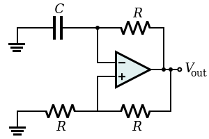
By using an RC network to add slow negative feedback to the inverting Schmitt trigger, a relaxation oscillator is formed. The feedback through the RC network causes the Schmitt trigger output to oscillate in an endless symmetric square wave (i.e., the Schmitt trigger in this configuration is an astable multivibrator).
References
- ^ "AN-49 Application Note, Rev. A" (PDF). Analog Devices. Retrieved 26 August 2017.
- ^ Chaniotakis; Cory (2006). "MIT OCW: Operational Amplifier Circuits: Comparators and Positive Feedback" (PDF). Massachusetts Institute of Technology. Retrieved 26 August 2017.
- ^ Kay, Art; Claycomb, Timothy (2014). "Comparator with Hysteresis Reference Design" (PDF). Texas Instruments. Retrieved 26 August 2017.
- ^ Elliott Sound Products Application Notes : Zero Crossing Detectors and Comparators