
In electrical engineering and mechanical engineering, a transient response is the response of a system to a change from an equilibrium or a steady state. The transient response is not necessarily tied to abrupt events but to any event that affects the equilibrium of the system. The impulse response and step response are transient responses to a specific input (an impulse and a step, respectively).
In electrical engineering specifically, the transient response is the circuit’s temporary response that will die out with time.[1] It is followed by the steady state response, which is the behavior of the circuit a long time after an external excitation is applied.[1]
YouTube Encyclopedic
-
1/3Views:345 84023 7133 680
-
Transient Analysis: First order R C and R L Circuits
-
Electrical Engineering: Ch 8: RC & RL Circuits (30 of 43) Transient and Steady State Response
-
Electrical Engineering: Transient Analysis (Series RL and RC Circuits)
Transcription
Damping
The response can be classified as one of three types of damping that describes the output in relation to the steady-state response.
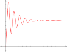
- Underdamped
- An underdamped response is one that oscillates within a decaying envelope. The more underdamped the system, the more oscillations and longer it takes to reach steady-state. Here damping ratio is always less than one.
- Critically damped
- A critically damped response is the response that reaches the steady-state value the fastest without being underdamped. It is related to critical points in the sense that it straddles the boundary of underdamped and overdamped responses. Here, the damping ratio is always equal to one. There should be no oscillation about the steady-state value in the ideal case.
- Overdamped
- An overdamped response is the response that does not oscillate about the steady-state value but takes longer to reach steady-state than the critically damped case. Here damping ratio is greater than one.
Properties

Transient response can be quantified with the following properties.
- Rise time
- Rise time refers to the time required for a signal to change from a specified low value to a specified high value. Typically, these values are 10% and 90% of the step height.
- Overshoot
- Overshoot is when a signal or function exceeds its target. It is often associated with ringing.
- Settling time
- Settling time is the time elapsed from the application of an ideal instantaneous step input to the time at which the output has entered and remained within a specified error band,[2] the time after which the following equality is satisfied:
- where is the steady-state value, and defines the width of the error band.
- Delay-time
- The delay time is the time required for the response to initially get halfway to the final value.[3]
- Peak time
- The peak time is the time required for the response to reach the first peak of the overshoot.[3]
- Steady-state error
- Steady-state error is the difference between the desired final output and the actual one when the system reaches a steady state, when its behavior may be expected to continue if the system is undisturbed.[4]


Oscillation
Oscillation is an effect caused by a transient stimulus to an underdamped circuit or system. It is a transient event preceding the final steady state following a sudden change of a circuit[5] or start-up. Mathematically, it can be modeled as a damped harmonic oscillator.
Inductor volt-second balance and capacitor ampere-second balance are disturbed by transients. These balances encapsulate the circuit analysis simplifications used for steady-state AC circuits.[6]
An example of transient oscillation can be found in digital (pulse) signals in computer networks.[7] Each pulse produces two transients, an oscillation resulting from the sudden rise in voltage and another oscillation from the sudden drop in voltage. This is generally considered an undesirable effect as it introduces variations in the high and low voltages of a signal, causing instability.
Electromagnetics
Electromagnetic pulses (EMP) occur internally as the result of the operation of switching devices. Engineers use voltage regulators and surge protectors to prevent transients in electricity from affecting delicate equipment. External sources include lightning, electrostatic discharge and nuclear electromagnetic pulse.
Within Electromagnetic compatibility testing, transients are deliberately administered to electronic equipment for testing their performance and resilience to transient interference. Many such tests administer the induced fast transient oscillation directly, in the form of a damped sine wave, rather than attempt to reproduce the original source. International standards define the magnitude and methods used to apply them.
The European standard for Electrical Fast Transient (EFT) testing is EN-61000-4-4. The U.S. equivalent is IEEE C37.90. Both of these standards are similar. The standard chosen is based on the intended market.
See also
References
- ^ a b Alexander, Charles K.; Sadiku, Matthew N. O. (2012). Fundamentals of Electric Circuits. McGraw Hill. p. 276.
- ^ Glushkov, V. M. Encyclopedia of Cybernetics (in Russian) (1 ed.). Kyiv: USE. p. 624.
- ^ a b Ogata, Katsuhiko (2002). Modern Control Engineering (4 ed.). Prentice-Hall. p. 230. ISBN 0-13-043245-8.
- ^ Lipták, Béla G. (2003). Instrument Engineers' Handbook: Process control and optimization (4th ed.). CRC Press. p. 108. ISBN 0-8493-1081-4.
- ^ Nilsson, James W, & Riedel, S. Electric Circuits, 9th Ed. Prentice Hall, 2010, p. 271.
- ^ Simon Ang, Alejandro Oliva, Power-Switching Converters, pp. 13–15, CRC Press, 2005 ISBN 0824722450.
- ^ Cheng, David K. Field and Wave Electromagnetics, 2nd Ed. Addison-Wesley, 1989, p. 471.