

In metalworking and woodworking, an automatic lathe is a lathe with an automatically controlled cutting process. Automatic lathes were first developed in the 1870s and were mechanically controlled. From the advent of NC and CNC in the 1950s, the term automatic lathe has generally been used for only mechanically controlled lathes, although some manufacturers (e.g., DMG Mori and Tsugami) market Swiss-type CNC lathes as 'automatic'.[3]
CNC has not yet entirely displaced mechanically automated lathes, as although no longer in production, many mechanically automated lathes remain in service.[4]
YouTube Encyclopedic
-
1/1Views:54 922
-
Different Types of Lathe Machines (3D Animation)
Transcription
General nomenclature
The term "automatic lathe" is still often used in manufacturing in its earlier sense, referring to automated lathes of non-CNC types. The first automatic lathes were mechanically automated and controlled by cams or tracers and pantographs. Thus, before electronic automation via numerical control, the "automatic" in the term "automatic machine tool" always referred implicitly to mechanical automation.
The earliest mechanically automated lathes were geometric lathes, including rose engine lathes. In industrial contexts during the Machine Age, the term "automatic lathe" referred to mechanical screw machines and chuckers.
Since the maturation of CNC, the implicit dichotomy of "manual versus automatic" still exists, but because CNC is so ubiquitous, the term "automatic" has lost some of its distinguishing power. All CNC machine tools are automatic, but the usage in the machining industries does not routinely call them by that term. The term "automatic", when it is used at all, still often refers implicitly to cam-operated machines. Thus a 2-axis CNC lathe is not referred to as an "automatic lathe" even if fully automated.
Small- to medium-sized cam-operated automatic lathes are usually called screw machines or automatic screw machines. These machines work on parts that (as a rough guide only) are up to 80 millimetres (3.1 in) in diameter and 300 millimetres (12 in) in length. Screw machines almost invariably do bar work, meaning a length of bar stock passes through the spindle and is gripped by the chuck (usually a collet chuck). As the part is being machined, the entire length of bar stock is rotated with the spindle. When the part is done, it is 'parted' from the bar, the chuck in released, the bar fed forward, and the chuck closed again, ready for the next cycle. The bar-feeding can happen by various means, including pulling-finger tools that grab the bar and pull or roller bar feed that pushes the bar from behind.
Larger cam-operated automatic lathes are usually called automatic chucking lathes, automatic lathes, automatic chuckers, automatics, or chuckers. The 'chucker' part of the name comes from the workpieces being discrete blanks, held in a bin called a "magazine", and each one takes a turn at being chucked and machined. (This is analogous to the way that each round of ammunition in the magazine of a semi-automatic pistol gets its turn at being chambered.) The blanks are either individual forgings or castings, or they are pre-sawn pieces of billet. However, some members of this family of machine tools turn bar work or work on centers (e.g., the Fay automatic lathe). Regarding bar work of large diameter (for example, 150 millimetres (5.9 in) or more), it is merely an academic point whether it is called "screw machine work" or just "automatic work".
Screw machine

Screw machines, being the class of automatic lathes for small- to medium-sized parts, are used in the high-volume manufacture of a vast variety of turned components. During the Swiss screw machining process, the workpiece is supported with a guide bushing, near the cutting tool.[5]
Speaking with reference to the normal definition of the term screw machine, all screw machines are fully automated, whether mechanically (via cams) or by CNC, which means that once they are set up and started, they continue running and producing parts with little human intervention. Mechanical automation came first, beginning in the 1870s; computerized control (via first NC and then CNC) came later, beginning in the 1950s.

The name screw machine is somewhat of a metonym, as screw machines can make parts other than screws or that are not threaded. However, the archetypal use for which screw machines were named was screw-making.
The definition of the term screw machine has changed with changing technology. Any use of the term prior to the 1840s, if it occurred, would have referred ad hoc to any machine tool used to produce screws. That is, there would have been no established differentiation from the term screw-cutting lathe. When turret lathes were developed in the 1840s, the term screw machine was applied to them in overlapping usage with the term turret lathe. In 1860, when some of the movements, such as turret indexing, were mechanically automated, the term automatic screw machine was applied, and the term hand screw machine or manual screw machine was retronymously applied to the earlier machines. Within 15 years, the entire part-cutting cycle had been mechanically automated, and machines of the 1860 type were retronymously called semi-automatic. From that time on, machines with fully automated cycles were usually called automatic screw machines, and eventually, in the usage of most people in the machining industries, the term screw machine no longer was used to refer to manual or semi-automatic turret lathes, having become reserved for one class of machine, the fully mechanically automated type. This narrow meaning of screw machine remained stable from about the 1890s until the 1950s. (Brown & Sharpe continued to call some of their hand-operated turret lathe models "screw machines", but most machinists reserved the term for automatics.) Within this class called screw machines there were variations, such as single-spindle versus multispindle, horizontal-turret versus vertical-turret, etc.
With the advent of NC, screw machines diverged into two classes, mechanical and NC. This distinction continues today with mechanical screw machines and CNC screw machines. However, in shop-floor jargon, the term screw machine by itself is still often understood in context to imply a mechanical screw machine, so the retronym mechanical screw machine is not consistently used.
Automatic chucker
An automatic chucking machine is similar to an automatic screw machine; both use spindles in production. The use of spindles, which are able to drill, bore and cut the workpiece, allows several functions simultaneously on both machines. A key difference between the machines is that the automatic chucker handles larger work, which due to its size is more often chucking work and less often bar work.[6] The Fay automatic lathe was a variant that specialized in turning work on centers. While a screw machine is limited to around 80 millimetres (3.1 in) practice, automatic chuckers are available that can handle up to 300 millimetres (12 in) chucks. The chucks are air-operated. Many of these machines are multispindle (more than one main spindle).
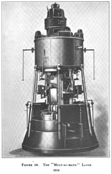
Well-known brands of such machines have included National-Acme, Hardinge, New Britain, New Britain-Gridley, Acme-Gridley, Davenport, Bullard Mult-Au-Matic (a vertical multispindle variant), and Thomas Ryder and Son.
Automatic chuckers are a class of machine tool specialized to narrow industry niches, such as OEM part suppliers to the automotive industry. They are limited in their economic niches to high-volume production of large parts, which tends to occur only at relatively few companies (compared to smaller work that may be done by small businesses). The market for such machine tools does not generally include local job shops or tool and die shops.
Cam-operated chuckers are fading into history faster than most other non-CNC machine tool classes. This is because the few companies that have them tend to be forced to continually adapt to the latest state of the art (today all CNC) to compete and survive. Cam-op chuckers may be more likely to be scrapped than other types of non-CNC machine tools. Unlike with "Grandpa's South Bend lathe" or "Dad's old Bridgeport knee mill", virtually no one can afford to keep and use them for sentimental reasons alone. As with most nondigital commercial typesetting machinery (such as Linotype machines).
Choice of machines and control type
Mechanical screw machines have been replaced to some extent by CNC lathes (turning centers) and CNC screw machines. However, they are still commonly in operation, and for high-volume production of turned components it is still often true that nothing is as cost-efficient as a mechanical screw machine.
In the hierarchy of manufacturing machines, the screw machine sits at the top when large product volumes are needed. An engine lathe sits at the bottom, taking the least time to set up but the most skilled labor and time to actually produce a part. A turret lathe has traditionally been one step above an engine lathe, needing greater set-up time but being able to produce a higher volume of product and usually requiring a lower-skilled operator once the set-up process is complete. Screw machines may require an extensive set-up, but once they are running, a single operator can monitor the operation of several machines.
The advent of the CNC lathe (or more properly, CNC turning center) has blurred these distinct levels of production to some extent. The CNC turning center most appropriately fits in the mid-range of production, replacing the turret lathe. However, it is often possible to produce a single component with a CNC turning center more quickly than can be done with an engine lathe. To some extent too, the CNC turning center has stepped into the region traditionally occupied by the (mechanical) screw machine. CNC screw machines do this to an even greater degree, but they are expensive. In some cases they are vital, yet in others a mechanical machine can match or beat overall performance and profitability. It is not unusual for cam-op automatic lathes to beat CNCs on cycle time.[4] CNC offers many benefits, not least CAD/CAM integration, but the CNC itself usually does not give any inherent speed advantage within the context of an automatic lathe cycle in terms of speeds and feeds or tool-changing speed. There are many variables involved in answering the question of which is best for a particular part at a particular company. (Overhead is part of the calculation—not least because most cam-op machines are long since paid for, whereas a late-model CNC machine has hefty monthly payments). Businesses relying on cam-op machines are still competing even in today's CNC-filled environment; they just need to be vigilant and smart about keeping it that way.[4]
In the multispindle segment, some machine tool builders also build hybrid machines that are part CNC and part old-school control (some stations are CNC while others are cam-op or actuated with simple hydraulic cycles). This lets shops with certain mixes of work derive competitive advantage from the lower cost compared with all-CNC machines.[7] The variety of machines that allow profitable production within certain niches reflects the variety of work that exists: some high-volume work remains the province of cam-op; full CNC with all the bells and whistles outcompetes on some flexible low-volume work; and hybrid machines may yield the lowest unit price on mixes in between.
Design

An automatic lathe may have a single spindle or multiple spindles. Each spindle contains a bar or blank of material that is being machined simultaneously. A common configuration is six spindles. The cage that holds these six bars of material indexes after each machining operation is complete. The indexing is reminiscent of a Gatling gun.
Each station may have multiple tools that cut the material in sequence. The tools are usually arranged in several axes, such as turret (rotary indexing), horizontal slide (linear indexing), and vertical slide (linear indexing). The linear groups are called "gangs". The operation of all these tools is similar to that on a turret lathe.
By way of example: a bar of material is fed forward through the spindle. The face of the bar is machined (facing operation). The outside of the bar is machined to shape (turning operation). The bar is drilled or bored, and finally, the part is cut off (parting operation).
In a single-spindle machine, these four operations would most likely be performed sequentially, with four cross-slides each coming into position in turn to perform their operation. In a multi-spindle machine, each station corresponds to a stage in the production sequence through which each piece is then cycled, all operations occurring simultaneously, but on different pieces of work, in the manner of an assembly line.

Operations
Form tools
For the machining of complex shapes, it is common to use form tools. This contrasts with the cutting that is performed on an engine lathe where the cutting tool is usually a single-point tool. A form tool has the form or contour of the final part but in reverse, so it cuts the material leaving the desired component shape. This contrasts to a single-point tool, which cuts on one point at a time and the shape of the component is dictated by the motion of the tool rather than its shape.
Threading
Unlike on a lathe, single-point threading is rarely if ever performed; it is too time-consuming for the short cycle times that are typical of screw machines. A self-releasing die head can rapidly cut or roll-form threads on outside diameters. A non-releasing tap holder with a tap can quickly cut inside diameters but it requires single spindle machines to reverse into high speed in order for the tap to be removed from the work. Threading and tapping speed (low speed) is typically 1/5 the high speed.
Rotary broaching
Rotary broaching is another common operation. The broach holder is mounted stationary while its internal live spindle and end cutting broach tool are driven by the workpiece. As the broach is fed into or around the workpiece, the broach's contact points are constantly changing, easily creating the desired form. The most common form made this way is a hexagonal socket in the end of a cap screw.
History


The history of automatic lathes in industrial contexts began with screw machines, and that history can only be truly understood within the context of screw making in general. Thus the discussion below begins with a simple overview of screw making in prior centuries, and how it evolved into 19th-, 20th-, and 21st-century practice.
Humans have been making screws since ancient times. For most of those centuries, screw making generally involved custom cutting of the threads of each screw by hand (via whittling or filing). Other ancient methods involved wrapping wire around a mandrel (such as a stick or metal rod) or carving a tree branch that had been spirally wrapped by a vine.
Various machine elements that potentially lent themselves to screw making (such as the lathe, the leadscrew, the slide rest, gears, slide rests geared direct to spindles, and "change gear" gear trains) were developed over the centuries, with some of those elements being quite ancient. Various sparks of inventive power during the Middle Ages and Renaissance combined some of these elements into screw-making machines that presaged the industrial era to follow. For example, various medieval inventors whose names are lost to history clearly worked on the problem, as shown by Wolfegg Castle's Medieval Housebook (written circa 1475–1490),[8] and Leonardo da Vinci and Jacques Besson left us with drawings of screw-cutting machines from the 1500s;[8] not all of these designs are known to have been built, but clearly similar machines were a reality during Besson's lifetime. However, it was not until 1760–1800[9] that these various elements were brought together successfully to create (in contemporaneous parallel) two new types of machine tool: the screw-cutting lathe (for low-volume, toolroom-style production of machine screws, with easy selection of various pitches) and the first high-volume-production, specialized, single-purpose machine tools for the production of screws, which were created to produce wood screws [meaning screws made of metal for use in wood] at high volume and low unit price. Screw-cutting lathes fed into the just-dawning evolution of modern machine shop practice, whereas the wood-screw-making machines fed into the just-dawning evolution of the modern hardware industry, that is, the concept of one factory supplying the needs of thousands of customers, who consumed screws in growing quantities for carpentry, cabinet making, and other trades, but did not make the hardware themselves (purchasing it instead from capital-intensive specialist makers for lower unit cost than they could achieve on their own). These two classes of machine tools simultaneously took the various classes of screws and moved them, for the first time, from the category of expensive, hand-made, seldom-used objects into the category of affordable, often-interchangeable commodity. (The interchangeability developed gradually, from intra-company to inter-company to national to international).
Between 1800 and 1840, on the machine-screw side, it became common practice to build all of the relevant screw-cutting machine elements into engine lathes, so the term "screw-cutting lathe" ceased to stand in contradistinction to other metalworking lathe types as a "special" kind of lathe. Meanwhile, on the wood-screw side, hardware manufacturers had developed for their own in-house use the first fully automatic [mechanically automated] special-purpose machine tools for the making of screws.[10] The 1760–1840 development arc was a tremendous technological advance, but later advancements would make screws even cheaper and more prevalent yet again. These began in the 1840s with the adaptation of the engine lathe with a turret-head toolholder to create the turret lathe. This development greatly reduced the time, effort, and skill needed from the machine operator to produce each machine screw. Single-pointing was forgone in favor of die head cutting for such medium- and high-volume repetitive production. Then, in the 1870s, the turret lathe's part-cutting cycle (sequence of movements) was automated by being put under cam control, in a way very similar to how music boxes and player pianos can play a tune automatically. According to Rolt (1965),[11] the first person to develop such a machine was Christopher Miner Spencer, a New England inventor. Charles Vander Woerd may have contemporarily independently invented a machine similar to Spencer's. However, the wood-screw-making machines of the 1840s and 1850s [special-purpose factory production machine tools as opposed to small-machine-shop machine tools], such as those developed by Cullen Whipple of the New England Screw Company and Thomas J. Sloan of the American Screw Company,[10] had anticipated the machines of Spencer and Vander Woerd in various ways, albeit approaching the problem of automated screw production from a different commercial angle. All of the above machine tools (i.e., screw-cutting lathes; suitably equipped engine lathes and bench lathes; turret lathes; turret-lathe-derived screw machines; and wood-screw-factory screw machines) were sometimes called "screw machines" during this era (logically enough, given that they were machines tailored to screw making). The nomenclatural evolution whereby the term "screw machine" is often used more narrowly than that is discussed above.
Spencer patented his idea in 1873; but his patent failed to protect the cam drum, which Spencer called the 'brain wheel'.[11] Therefore, many other people quickly took up the idea. Later important developers of fully automatic lathes included S. L. Worsley, who developed a single-spindle machine for Brown & Sharpe,[11] Edwin C. Henn, Reinhold Hakewessel, and George O. Gridley, who developed multiple-spindle variants and who was involved with a succession of corporations (Acme, National, National-Acme, Windsor Machine Company, Acme-Gridley, New Britain-Gridley);[11][12][13] Edward P. Bullard Jr, who led the development of the Bullard Mult-Au-Matic;[2][14] F.C. Fay and Otto A. Schaum, who developed the Fay automatic lathe;[15] Ralph Flanders and his brother Ernest, who further refined the Fay lathe[15] and developed the automatic screw thread grinder. Meanwhile, engineers in Switzerland were also developing new manually and automatically controlled lathes. The technological developments in America and Switzerland flowed rapidly into other industrialized countries (via routes such as machine tool exports; trade journal articles and advertisements; trade shows, from world's fairs to regional events; and the turnover and emigration of engineers, setup hands, and operators). There, local innovators also developed further tooling for the machines and built clone machine models.
The development of numerical control was the next major leap in the history of automatic lathes—and it is also what changed the paradigm of what the "manual versus automatic" distinction meant. Beginning in the 1950s, NC lathes began to replace manual lathes and cam-op screw machines, although the displacement of the older technology by CNC has been a long, gradual arc that even today is not a total eclipse. By the 1980s, true CNC screw machines (as opposed to simpler CNC lathes), Swiss-style and non-Swiss, had begun to make serious inroads into the realm of cam-op screw machines. Similarly, CNC chuckers were developed, eventually evolving even into CNC rotary transfer machines. These machine tools are little known outside the automotive manufacturing sector.
References
- ^ ASME 1921.
- ^ a b Roe 1916, p. 276 ff.
- ^ Bralla, James (2007), Handbook of Manufacturing Processes, New York: Industrial Press, p. Page 91, heading "Swiss-type screw machines", ISBN 9780831191474.
- ^ a b c Donohue, Barbara (November–December 2010), ""How it Works" series: Competing Successfully Using Older Equipment", Today's Machining World, 6 (9), archived from the original on 2011-02-17.
- ^ Engineering, Ardel. "Swiss Turning Capabilities | Ardel Engineering". www.ardelengineering.com. Retrieved 2018-03-12.
- ^ MachineSales.com (2013-08-20). "The Automatic Chucker: Its Place In The Machining Industry". . Machinery Blog. Retrieved 2018-03-12.
- ^ Koepfer, Chris (2014-08-18), "Hybrid Multi-Spindle: Look Ma, No Cams", Production Machining, 14 (9).
- ^ a b Rybczynski 2000, pp. 87–97.
- ^ Rybczynski 2000, pp. 75–99.
- ^ a b Rybczynski 2000, pp. 75–78.
- ^ a b c d Rolt 1965, pp. 169–170.
- ^ Roe 1937, pp. 103–108.
- ^ Rose 1990, pp. 564–565.
- ^ American Precision Museum 1982
- ^ a b Roe 1937, p. 42.
Bibliography
- American Precision Museum (1982), "Edward P. Bullard (1872–1953)", Machine Tool Hall of Fame, American Precision Museum, archived from the original on 2010-08-07, retrieved 2010-11-29
- ASME (1921), A.S.M.E. mechanical catalog and directory, Volume 11, American Society of Mechanical Engineers.
- Roe, Joseph Wickham (1916), English and American Tool Builders, New Haven, Connecticut: Yale University Press, LCCN 16011753. Reprinted by McGraw-Hill, New York and London, 1926 (LCCN 27-24075); and by Lindsay Publications, Inc., Bradley, Illinois (ISBN 978-0-917914-73-7).
- Roe, Joseph Wickham (1937), James Hartness: A Representative of the Machine Age at Its Best, New York: American Society of Mechanical Engineers, LCCN 37016470, OCLC 3456642. link from HathiTrust.
- Rolt, L. T. C. (1965), A Short History of Machine Tools, Cambridge, Massachusetts, USA: MIT Press, OCLC 250074. Co-edition published as Rolt, L. T. C. (1965), Tools for the Job: a Short History of Machine Tools, London: B. T. Batsford, LCCN 65080822.
- Rose, William (1990), Cleveland: the making of a city, Kent State University Press, ISBN 978-0-87338-428-5
- Rybczynski, Witold (2000), One Good Turn: A Natural History of the Screwdriver and the Screw, Scribner, ISBN 978-0-684-86729-8, LCCN 00036988, OCLC 462234518. Various republications (paperback, e-book, braille, etc).
- Smid, Peter (2008), CNC Programming Handbook (3rd ed.), New York: Industrial Press, ISBN 9780831133474, LCCN 2007045901.
External links
- YouTube video showing a 1965 cam-op screw machine in action.
- YouTube video showing another cam-op screw machine.