
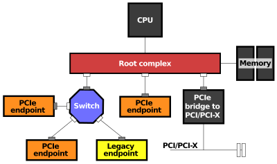
In a PCI Express (PCIe) system, a root complex device connects the CPU and memory subsystem to the PCI Express switch fabric composed of one or more PCIe or PCI devices.
Similar to a host bridge in a PCI system,[2] the root complex generates transaction requests on behalf of the CPU, which is interconnected through a local bus. Root complex functionality may be integrated in the chipset and/or the CPU. A root complex may contain more than one PCI Express port and multiple switch devices can be connected to ports on the root complex or cascaded.[3]
YouTube Encyclopedic
-
1/3Views:2 1005 0832 983
-
Finding nth Roots of a Complex Number
-
Casio fx-115ES PLUS bonus features (n-th root, complex number, log with any base)
-
Shortcut For Square Root Of A Complex Number By- Sumit Luthra
Transcription
Device Memory Map
The PCIe Root Complex holds a master copy of a 'Type 1 Configuration Table' that defines the host memory space that is accessible from each Endpoint device. In addition, each PCIe Endpoint device holds a master copy of their own memory space map in the host system memory as a 'Type 0 Configuration Table', this configuration table in each device allows the host to access the local memory of a PCIe device. Both the Type 1 and Type 0 configuration tables are set up by the Host Operating System that controls the Root Complex by a process known as enumeration and which acts to build a device memory map for the system by querying each bridge, and endpoint device connected on the bus network. Similarly, a PCIe Bridge acts a tiered root complex with a "Type 0 Configuration Table".
References
- ^ Richard Solomon (2015-06-17). "PCI Express Basics and Background" (PDF). PCI-SIG. p. 26. Retrieved 2016-04-12.
- ^ "Bus Specifics (Writing Device Drivers)". docs.oracle.com. Retrieved 2020-11-14.
- ^ "Choosing the Right Programmable Logic Solution for PCI Express Applications". Archived from the original on 21 February 2011. Retrieved 31 March 2010.
This computer hardware article is a stub. You can help Wikipedia by expanding it. |