

In optics, a ray is an idealized geometrical model of light or other electromagnetic radiation, obtained by choosing a curve that is perpendicular to the wavefronts of the actual light, and that points in the direction of energy flow.[1][2] Rays are used to model the propagation of light through an optical system, by dividing the real light field up into discrete rays that can be computationally propagated through the system by the techniques of ray tracing. This allows even very complex optical systems to be analyzed mathematically or simulated by computer. Ray tracing uses approximate solutions to Maxwell's equations that are valid as long as the light waves propagate through and around objects whose dimensions are much greater than the light's wavelength. Ray optics or geometrical optics does not describe phenomena such as diffraction, which require wave optics theory. Some wave phenomena such as interference can be modeled in limited circumstances by adding phase to the ray model.
YouTube Encyclopedic
-
1/3Views:404 2064 5003 899
-
Thin lens equation and problem solving | Geometric optics | Physics | Khan Academy
-
Geometric Optics Basics
-
Geometrical Optics with COMSOL Multiphysics - Ray Tracing - Thin Lens - Lensmaker's Formula
Transcription
- [Voiceover] When you're dealing with these thin lenses, you're going to have to use this formula right here, one over f equals one over d-o plus one over d-i. Not too bad, except when are these positive or negative? Let's find out. F is the focal length. The focal length, when you've got a thin lens, there's a focal point on each side of the lens. The focal length is the distance from the center of the lens to one of these focal points. Which one, it's doesn't actually matter, because if you want to know whether the focal length is positive or negative, all you have to look at is what type of lens you have. In this case, we've got a convex lens, also known as a converging lens. It turns out, for these types of lenses, the focal length is always, always, going to be positive. If this focal length right here was, say, eight centimeters, we would plug in positive eight centimeters. It doesn't matter, we could have measured on this side. This side will be eight centimeters. We still plug in positive eight centimeters into this focal length if it is a converging, or a convex, lens. If you had the other type of lens ... Here's the other kind. This one is either diverging or it's going to be concave. If you have a concave or diverging lens, it also will have two focal points typically drawn on either side. These will be a certain distance along that principal axis to the center of the lens. If you measured this, by definition for a concave or a diverging lens, the focal length is always going to be a negative focal length. So, if this distance here was eight centimeters, you'd have to plug in negative eight centimeters up here into the focal length. All you need to look at is what type of lens you have. D-o, d-i, doesn't matter. D-o and d-i could be big, small, positive, negative. You could have a real image, a virtual image. It doesn't matter. All you have to look at is what type of lens you have. That will tell you whether you should plug in a positive focal length, or a negative focal length. All right, so focal length isn't too bad. How about d-o? D-o represents the object distance. If I had an object over here, and we always draw objects as arrows. That lets us know whether they're right-side up or upside down. Here's my object. The object distance refers to the distance from, always measured from the center of the lens to where the thing is, and in this case the thing is the object, so here's my d-o. This object distance ... this one's even easier ... object distance, just always positive. So my object distance, I'm just always going to make that positive. If this is 30 centimeters, I'm plugging in positive 30 centimeters over there. If it's 40 centimeters, positive 40 centimeters. Always going to be positive unless ... there is one exception. If you had multiple lenses it's possible you might have to deal with a negative object distance, but, if you're dealing with a single lens, whether it's concave or convex, I don't care what kind of lens it is, if it's a single lens, your object distance is going to be a positive distance if you only have one lens. Okay, so object distance is even easier. Always positive, no matter what the case is, if you have a single lens. How about image distance? Image distance is the tricky one. This refers to the distance from the lens to where the image is, but your image can be on one side or the other. Let's see here, let's say for this case over here I ended up with an image upside down over here, something like this. Say this is my image that was formed by this object in this converging, convex, lens. Image distance is defined to be from the center of the lens to where my image is, always measured parallel to this principal axis. Sometimes people get confused. They think, well, am I supposed to measure from the center here on this diagonal line? No, you never do that! You always go from the center, parallel to the principal axis, to where the image is. This is defined to be the image distance. When will this be positive and negative? Here's the tricky one, so be careful. Image distance will be positive if the image distance is on this other side of the lens than the object. One way to remember it is image distance will be positive if it's on the opposite side of the lens as the object, or, the way I like to remember it, if you're using this lens right, you should be looking, your eye should be looking through the lens at the object. Putting your eye over here does no good at all. Really, your lens is kind of pointless now. If my eye's over here, I'm looking at my object, and I'm just holding a lens in front of it. This is really doing no good. So I don't want my eye over there. If I'm using this lens right, my eye would be over on this side, and I'd be looking at this object, I'd be looking through. I'm not shooting light rays out of my eyes, but I'm looking in this direction through the lens at my object. I wouldn't see the object. What I would actually see is an image of the object, I'd see this image right here, but still, I'm trying to look through the lens. A way to remember if the image distance is positive, if this image distance has been brought closer to your eye than the object was, if it's on the side of this lens that your eye is on, that will be a positive image distance. So if it's on this, in this case, the right side, but what's important is it's on the opposite side of the object, and the same side as your eye, that's when image distance will be positive. That'll be true regardless, whether you've got a concave, convex, converging, diverging. If the image is on the same side as your eye over here, then it should be a positive image distance. Now, for this diverging case, maybe the image ended up over here somewhere. I'm going to draw an image over here. Again, image distance from the lens, center of the lens, to where your image is, so I'm going to draw that line. This would be my image distance. In this case, my eye still should be on this side. My eye's on this side because I should be looking through my lens at my object. I'm looking through the lens at the object. I'd see this image because this image is on the opposite side of the lens as my eye, or, another way to think about it, it's on the same side of the object. This would be a negative image distance. I'd have to plug in a negative number, or if I got a negative number out of this formula for d-i, I would know that that image is formed on the opposite side of the lens as my eye. Those are the sign conventions for using this thin lens formula. But notice something. This formula's only giving you these horizontal distances. It tells you nothing about how tall the image should be, or how tall the object is. It only tells you these horizontal distances. To know about the height, you'd have to use a different formula. That other formula was this magnification formula. It said the magnification, M, equals negative the image distance. If you took the image distance and then divided by the object distance you'd get the magnification. So we notice something. We notice something important here. If the image distance comes out negative, we'd have magnification as negative of another negative number, object distance always positive, so we'd have a negative of a negative, that would give us a positive. If our image distance comes out negative like it did down here, then we'd get a positive magnification and positive magnification means you've got a right-side up image, if it's positive. If our image distance came out to be positive, like on this side, if we had a positive image distance, we'd have a negative of a positive number, that would give us a negative magnification. That means it's upside down. So it's important to note if our image distance comes out negative, negative image distance means not inverted, and positive image distance means that it is inverted from whatever it was originally. Let's look at a few examples. Say you got this example. It said find the image distance, and it just gave you this diagram. We're going to have to use this thin lens formula. We'll have to figure out what f is, f, the focal length. We've got these two focal lengths, here, eight centimeters on both sides. Should I make it a positive eight centimeters or a positive eight centimeters? Remember, the rule is that you just look at what type of lens you have. In this case, I have a concave lens, or another way of saying that is a diverging lens. Because I have that type of lens it doesn't matter. I don't have to look at anything else. I automatically know my focal length is going to be one over negative eight centimeters. One over negative eight centimeters equals one over the object distance, here we go, object over here, 24 centimeters away. Should I make it positive or negative? I've only got one lens here. That means object distance is always going to be positive. So that's one over positive 24 centimeters. Now we can solve for our image distance. One over d-i. If I use algebra to solve here I'll have one over negative eight centimeters minus one over 24 centimeters, and note, I can put this all in terms of centimeters, I can put it all in terms of meters. It doesn't matter what units I use here. Those are the units I'll get out. I just have to make sure I'm consistent. So if I solve this on the left-hand side, turns out you'll get negative one over six centimeters equals, well, that's not what d-i equals. That's what one over d-i equals, so don't forget at the very end you have to take one over both sides. If you take one over both sides, my d-i turns out to be negative six centimeters. What does that mean? D-i of negative six centimeters. That means my image is going to be six centimeters away from the lens, and the negative means it's going to be on the opposite side as my eye or the same side as my object. My eye's going to be over here. If I'm using this lens right, I've got my eye right here looking for the image. The negative image distance means it's going to be over on the left-hand side, where? Six means six centimeters and away from what? Everything's measured from the center of the lens, and so from here to there would be six centimeters. This tells me on my principal axis, my image is going to be right around here, six centimeters away from the lens, but it doesn't tell me, note, this does not tell me how high the image is going to be, how tall, whether it's right-side up ... Actually, hold on. It does tell us whether it's right-side up. This came out to be negative. Remember our rule? Negative image distances means it's got to be right-side up. I'm going to have a right-side up image, but I don't know how tall yet. I'm going to have to use the magnification equation to figure that out. I'll come over here. Magnification is negative d-i over d-o. What was my d-i? Negative of d-i was negative six, so I'm going to plug in negative six centimeters. On the bottom, I'm going to plug in, let's see, it was 24 centimeters was my object distance. What does that give me? Negative cancels the negative, I get positive, and I get positive one-fourth. Positive one-fourth. Remember, here, positive magnification means right-side up. One-fourth means that my image is going to be a fourth the size of my object. If my object were, say, eight centimeters tall, my image would only be two centimeters tall. I'm going to draw an image here that's right-side up, right-side up because I got a positive, and it's got to be a fourth as big as my object, so let's see, one-fourth might be around here, so it's got to be right-side up and about a fourth as big. I'd get a really little image. It'd be right around there. That's what I would see when I looked through this lens. That's an example of using the thin lens equation and the magnification equation.
Definition
A light ray is a line (straight or curved) that is perpendicular to the light's wavefronts; its tangent is collinear with the wave vector. Light rays in homogeneous media are straight. They bend at the interface between two dissimilar media and may be curved in a medium in which the refractive index changes. Geometric optics describes how rays propagate through an optical system. Objects to be imaged are treated as collections of independent point sources, each producing spherical wavefronts and corresponding outward rays. Rays from each object point can be mathematically propagated to locate the corresponding point on the image.
A slightly more rigorous definition of a light ray follows from Fermat's principle, which states that the path taken between two points by a ray of light is the path that can be traversed in the least time.[3]
Special rays
There are many special rays that are used in optical modelling to analyze an optical system. These are defined and described below, grouped by the type of system they are used to model.
Interaction with surfaces
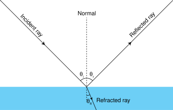


- An incident ray is a ray of light that strikes a surface. The angle between this ray and the perpendicular or normal to the surface is the angle of incidence.
- The reflected ray corresponding to a given incident ray, is the ray that represents the light reflected by the surface. The angle between the surface normal and the reflected ray is known as the angle of reflection. The Law of Reflection says that for a specular (non-scattering) surface, the angle of reflection is always equal to the angle of incidence.
- The refracted ray or transmitted ray corresponding to a given incident ray represents the light that is transmitted through the surface. The angle between this ray and the normal is known as the angle of refraction, and it is given by Snell's Law. Conservation of energy requires that the power in the incident ray must equal the sum of the power in the refracted ray, the power in the reflected ray, and any power absorbed at the surface.
- If the material is birefringent, the refracted ray may split into ordinary and extraordinary rays, which experience different indexes of refraction when passing through the birefringent material.
Optical systems

- A meridional ray or tangential ray is a ray that is confined to the plane containing the system's optical axis and the object point from which the ray originated.[4]
- A skew ray is a ray that does not propagate in a plane that contains both the object point and the optical axis. Such rays do not cross the optical axis anywhere and are not parallel to it.[4]
- The marginal ray (sometimes known as an a ray or a marginal axial ray) in an optical system is the meridional ray that starts at the point where an object to be imaged crosses the optical axis (the axial object point) and touches an edge of the aperture stop of the system.[5][6][7] This ray is useful, because it crosses the optical axis again at the locations where a real image will be formed, and backward extensions of the ray's path cross the axis where a virtual image will be formed. Since the entrance pupil and exit pupil are images of the aperture stop, for real image pupils, the distance of the marginal ray from the optical axis at the pupil locations defines the sizes of each pupil. For virtual image pupils, an extended line, forward along the marginal ray before the first optical element or backward along the marginal ray before the last optical element, determines the size of the entrance or exit pupil, respectively.
- The principal ray or chief ray (sometimes known as the b ray) in an optical system is the meridional ray that starts at an edge of an object and passes through the center of the aperture stop.[5][8][7] The distance between the chief ray (or an extension of it for a virtual image) and the optical axis at an image location defines the size of the image. This ray (or forward and backward extensions of it for virtual image pupils) crosses the optical axis at the locations of the entrance and exit pupils. The marginal and chief rays together define the Lagrange invariant, which characterizes the throughput or etendue of the optical system.[9] Some authors define a "principal ray" for each object point, and in this case, the principal ray starting at an edge point of the object may then be called the marginal principal ray.[6]
- A sagittal ray or transverse ray from an off-axis object point is a ray that propagates in the plane that is perpendicular to the meridional plane and contains the principal ray.[4] Sagittal rays intersect the pupil along a line that is perpendicular to the meridional plane for the ray's object point and passes through the optical axis. If the axis direction is defined to be the z axis, and the meridional plane is the y-z plane, sagittal rays intersect the pupil at yp= 0. The principal ray is both sagittal and meridional.[4] All other sagittal rays are skew rays.
- A paraxial ray is a ray that makes a small angle to the optical axis of the system, and lies close to the axis throughout the system.[10] Such rays can be modeled reasonably well by using the paraxial approximation. When discussing ray tracing this definition is often reversed: a "paraxial ray" is then a ray that is modeled using the paraxial approximation, not necessarily a ray that remains close to the axis.[11][12]
- A finite ray or real ray is a ray that is traced without making the paraxial approximation.[12][13]
- A parabasal ray is a ray that propagates close to some defined "base ray" rather than the optical axis.[14] This is more appropriate than the paraxial model in systems that lack symmetry about the optical axis. In computer modeling, parabasal rays are "real rays", that is rays that are treated without making the paraxial approximation. Parabasal rays about the optical axis are sometimes used to calculate first-order properties of optical systems.[15]
Fiber optics
- A meridional ray is a ray that passes through the axis of an optical fiber.
- A skew ray is a ray that travels in a non-planar zig-zag path and never crosses the axis of an optical fiber.
- A guided ray, bound ray, or trapped ray is a ray in a multi-mode optical fiber, which is confined by the core. For step index fiber, light entering the fiber will be guided if it makes an angle with the fiber axis that is less than the fiber's acceptance angle.
- A leaky ray or tunneling ray is a ray in an optical fiber that geometric optics predicts would totally reflect at the boundary between the core and the cladding, but which suffers loss due to the curved core boundary.
Geometrical optics
Geometrical optics, or ray optics, is a model of optics that describes light propagation in terms of rays. The ray in geometrical optics is an abstraction useful for approximating the paths along which light propagates under certain circumstances.
The simplifying assumptions of geometrical optics include that light rays:
- propagate in straight-line paths as they travel in a homogeneous medium
- bend, and in particular circumstances may split in two, at the interface between two dissimilar media
- follow curved paths in a medium in which the refractive index changes
- may be absorbed or reflected.
Ray tracing
In physics, ray tracing is a method for calculating the path of waves or particles through a system with regions of varying propagation velocity, absorption characteristics, and reflecting surfaces. Under these circumstances, wavefronts may bend, change direction, or reflect off surfaces, complicating analysis. Strictly speaking Ray tracing is when analytic solutions to the ray's trajectories are solved; however Ray tracing is often confused with ray-marching which numerically solves problems by repeatedly advancing idealized narrow beams called rays through the medium by discrete amounts. Simple problems can be analyzed by propagating a few rays using simple mathematics. More detailed analysis can be performed by using a computer to propagate many rays.
When applied to problems of electromagnetic radiation, ray tracing often relies on approximate solutions to Maxwell's equations that are valid as long as the light waves propagate through and around objects whose dimensions are much greater than the light's wavelength. Ray theory does not describe phenomena such as interference and diffraction, which require wave theory (involving the phase of the wave).See also
- Collimated beam
- Optical path
- Optical path length
- Paraxial approximation
- Pencil beam
- Ray transfer matrix analysis
References
- ^ Moore, Ken (25 July 2005). "What is a ray?". ZEMAX Users' Knowledge Base. Retrieved 30 May 2008.
- ^ Greivenkamp, John E. (2004). Field Guide to Geometric Optics. SPIE Field Guides. p. 2. ISBN 0819452947.
- ^ Arthur Schuster, An Introduction to the Theory of Optics, London: Edward Arnold, 1904 online.
- ^ a b c d Stewart, James E. (1996). Optical Principles and Technology for Engineers. CRC. p. 57. ISBN 978-0-8247-9705-8.
- ^ a b Greivenkamp, John E. (2004). Field Guide to Geometrical Optics. SPIE Field Guides vol. FG01. SPIE. ISBN 0-8194-5294-7., p. 25 [1].
- ^ a b Riedl, Max J. (2001). Optical Design Fundamentals for Infrared Systems. Tutorial texts in optical engineering. Vol. 48. SPIE. p. 1. ISBN 978-0-8194-4051-8.
- ^ a b Hecht, Eugene (2017). "5.3.2 Entrance and Exit Pupils". Optics (5th ed.). Pearson. p. 184. ISBN 978-1-292-09693-3.
- ^ Malacara, Daniel and Zacarias (2003). Handbook of Optical Design (2nd ed.). CRC. p. 25. ISBN 978-0-8247-4613-1.
- ^ Greivenkamp (2004), p. 28 [2].
- ^ Greivenkamp (2004), pp. 19–20 [3].
- ^ Nicholson, Mark (21 July 2005). "Understanding Paraxial Ray-Tracing". ZEMAX Users' Knowledge Base. Retrieved 17 August 2009.
- ^ a b Atchison, David A.; Smith, George (2000). "A1: Paraxial optics". Optics of the Human Eye. Elsevier Health Sciences. p. 237. ISBN 978-0-7506-3775-6.
- ^ Welford, W. T. (1986). "4: Finite Raytracing". Aberrations of Optical Systems. Adam Hilger series on optics and optoelectronics. CRC Press. p. 50. ISBN 978-0-85274-564-9.
- ^ Buchdahl, H. A. (1993). An Introduction to Hamiltonian Optics. Dover. p. 26. ISBN 978-0-486-67597-8.
- ^ Nicholson, Mark (21 July 2005). "Understanding Paraxial Ray-Tracing". ZEMAX Users' Knowledge Base. p. 2. Retrieved 17 August 2009.