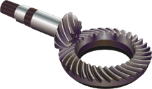
A spiral bevel gear is a bevel gear with helical teeth. The main application of this is in a vehicle differential, where the direction of drive from the drive shaft must be turned 90 degrees to drive the wheels. The helical design produces less vibration and noise than conventional straight-cut or spur-cut gear with straight teeth.
A spiral bevel gear set should always be replaced in pairs i.e. both the left hand and right hand gears should be replaced together since the gears are manufactured and lapped in pairs.
YouTube Encyclopedic
-
1/3Views:67 08075 5454 928
-
spiral gear
-
WWW.EIRSA.COM - GLEASON 114 HYPOID GEAR CUTTING SPIRAL BEVEL
-
Spiral Bevel Pinion Cutting
Transcription
Handedness


A right hand spiral bevel gear is one in which the outer half of a tooth is inclined in the clockwise direction from the axial plane through the midpoint of the tooth as viewed by an observer looking at the face of the gear.
A left hand spiral bevel gear is one in which the outer half of a tooth is inclined in the counterclockwise direction from the axial plane through the midpoint of the tooth as viewed by an observer looking at the face of the gear.
Note that a spiral bevel gear and pinion are always of opposite hand, including the case when the gear is internal.
Also note that the designations right hand and left hand are applied similarly to other types of bevel gear, hypoid gears, and oblique tooth face gears.[1]
Hypoid gears

A hypoid is a type of spiral bevel gear whose axis does not intersect with the axis of the meshing gear. The shape of a hypoid gear is a revolved hyperboloid (that is, the pitch surface of the hypoid gear is a hyperbolic surface), whereas the shape of a spiral bevel gear is normally conical. The hypoid gear places the pinion off-axis to the crown wheel (ring gear) which allows the pinion to be larger in diameter and have more contact area. In hypoid gear design, the pinion and gear are practically always of opposite hand, and the spiral angle of the pinion is usually larger than that of the gear. The hypoid pinion is then larger in diameter than an equivalent bevel pinion.
A hypoid gear incorporates some sliding and can be considered halfway between a straight-cut gear and a worm gear. Special gear oils are required for hypoid gears because the sliding action requires effective lubrication under extreme pressure between the teeth.
Hypoid gearings are used in power transmission products that are more efficient than conventional worm gearing.[citation needed] They are considerably stronger in that any load is conveyed through multiple teeth simultaneously. By contrast, bevel gears are loaded through one tooth at a time. The multiple contacts of hypoid gearing, with proper lubrication, can be nearly silent, as well.
Spiral angle

The spiral angle in a spiral bevel gear is the angle between the tooth trace and an element of the pitch cone, and corresponds to the helix angle in helical teeth. Unless otherwise specified, the term spiral angle is understood to be the mean spiral angle.
- Mean spiral angle is the specific designation for the spiral angle at the mean cone distance in a bevel gear.
- Outer spiral angle is the spiral angle of a bevel gear at the outer cone distance.
- Inner spiral angle is the spiral angle of a bevel gear at the inner cone distance.

Comparison of spiral bevel gears to hypoid gears
Hypoid gears are stronger, operate more quietly and can be used for higher reduction ratios, however they also have some sliding action along the teeth, which reduces mechanical efficiency, the energy losses being in the form of heat produced in the gear surfaces and the lubricating fluid.
Hypoid gears are typically used in rear-drive automobile drivetrains.
A higher hypoid offset allows the gear to transmit higher torque. However increasing the hypoid offset results in reduction of mechanical efficiency and a consequent reduction in fuel economy. For practical purposes, it is often impossible to replace low efficiency hypoid gears with more efficient spiral bevel gears in automotive use because the spiral bevel gear would need a much larger diameter to transmit the same torque. Increasing the size of the drive axle gear would require an increase of the size of the gear housing and a reduction in the ground clearance, interior space, and an increase in weight.
The hypoid gear is also commonly used in some railcar transmissions with diesel power units - where the engine and gearbox are similar to those used in traditional trucks and busses (not diesel/electric hybrid type drive). The transmission, to allow the input shaft to always rotate in one specific direction (either clockwise or anti-clockwise) while allowing the output shafts to change their rotational direction; thus allowing a vehicle to drive either direction.
Another advantage of hypoid gear is that the ring gear of the differential and the input pinion gear are both hypoid. In most passenger cars this allows the pinion to be offset to the bottom of the crown wheel. This provides for longer tooth contact and allows the shaft that drives the pinion to be lowered, reducing the "hump" intrusion in the passenger compartment floor. However, the greater the displacement of the input shaft axis from the crown wheel axis, the lower the mechanical efficiency.
See also
References
- ^ Gear Nomenclature, Definition of Terms with Symbols. American Gear Manufacturers Association. 2005. p. 72. ISBN 1-55589-846-7. OCLC 65562739. ANSI/AGMA 1012-G05.
