
Solar-cell efficiency refers to the portion of energy in the form of sunlight that can be converted via photovoltaics into electricity by the solar cell.
The efficiency of the solar cells used in a photovoltaic system, in combination with latitude and climate, determines the annual energy output of the system. For example, a solar panel with 20% efficiency and an area of 1 m2 will produce 200 kWh/yr at Standard Test Conditions if exposed to the Standard Test Condition solar irradiance value of 1000 W/m2 for 2.74 hours a day. Usually solar panels are exposed to sunlight for longer than this in a given day, but the solar irradiance is less than 1000 W/m2 for most of the day. A solar panel can produce more when the Sun is high in Earth's sky and will produce less in cloudy conditions or when the Sun is low in the sky, usually the Sun is lower in the sky in the winter.
Two location dependant factors that affect solar PV yield are the dispersion and intensity of solar radiation. These two variables can vary greatly between each country.[1] The global regions that have high radiation levels throughout the year are the middle east, Northern Chile, Australia, China, and Southwestern USA.[1][2] In a high-yield solar area like central Colorado, which receives annual insolation of 2000 kWh/m2/year,[3] a panel can be expected to produce 400 kWh of energy per year. However, in Michigan, which receives only 1400 kWh/m2/year,[3] annual energy yield will drop to 280 kWh for the same panel. At more northerly European latitudes, yields are significantly lower: 175 kWh annual energy yield in southern England under the same conditions.[4]
Several factors affect a cell's conversion efficiency, including its reflectance, thermodynamic efficiency, charge carrier separation efficiency, charge carrier collection efficiency and conduction efficiency values.[6][5] Because these parameters can be difficult to measure directly, other parameters are measured instead, including quantum efficiency, open-circuit voltage (VOC) ratio, and § Fill factor. Reflectance losses are accounted for by the quantum efficiency value, as they affect "external quantum efficiency". Recombination losses are accounted for by the quantum efficiency, VOC ratio, and fill factor values. Resistive losses are predominantly accounted for by the fill factor value, but also contribute to the quantum efficiency and VOC ratio values.
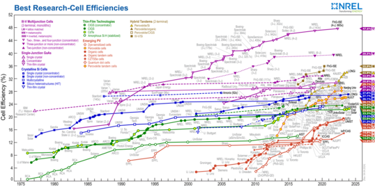
As of 2024, the world record for solar cell efficiency is 47.6%, set in May 2022 by Fraunhofer ISE, with a III-V four-junction CPV cell.[7] This beat the previous record of 47.1%, set in 2019 by multi-junction concentrator solar cells developed at National Renewable Energy Laboratory (NREL), Golden, Colorado, USA,[8] which was set in lab conditions, under extremely concentrated light. The record in real-world conditions is also held by NREL, who developed triple junction cells with a tested efficiency of 39.5%.[9][10]
YouTube Encyclopedic
-
1/5Views:9 426671 2211 824 8583 70547 418
-
Solar Cell Efficiency
-
Solar 4.0: Ultra Efficient Solar Panel Breakthrough
-
Exploring Solar Panel Efficiency Breakthroughs in 2022
-
Breakthrough in Solar Panel Efficiency - Ferroelectric Materials Now 1000x Better
-
New NREL Solar Cell breaks all Efficiency Records!
Transcription
Factors affecting energy conversion efficiency
The factors affecting energy conversion efficiency were expounded in a landmark paper by William Shockley and Hans Queisser in 1961.[11] See Shockley–Queisser limit for more detail.
Thermodynamic-efficiency limit and infinite-stack limit

If one has a source of heat at temperature Ts and cooler heat sink at temperature Tc, the maximum theoretically possible value for the ratio of work (or electric power) obtained to heat supplied is 1-Tc/Ts, given by a Carnot heat engine. If we take 6000 K for the temperature of the sun and 300 K for ambient conditions on earth, this comes to 95%. In 1981, Alexis de Vos and Herman Pauwels showed that this is achievable with a stack of an infinite number of cells with band gaps ranging from infinity (the first cells encountered by the incoming photons) to zero, with a voltage in each cell very close to the open-circuit voltage, equal to 95% of the band gap of that cell, and with 6000 K blackbody radiation coming from all directions. However, the 95% efficiency thereby achieved means that the electric power is 95% of the net amount of light absorbed – the stack emits radiation as it has non-zero temperature, and this radiation has to be subtracted from the incoming radiation when calculating the amount of heat being transferred and the efficiency. They also considered the more relevant problem of maximizing the power output for a stack being illuminated from all directions by 6000 K blackbody radiation. In this case, the voltages must be lowered to less than 95% of the band gap (the percentage is not constant over all the cells). The maximum theoretical efficiency calculated is 86.8% for a stack of an infinite number of cells, using the incoming concentrated sunlight radiation.[12] When the incoming radiation comes only from an area of the sky the size of the sun, the efficiency limit drops to 68.7%.[13]
Ultimate efficiency
Normal photovoltaic systems however have only one p–n junction and are therefore subject to a lower efficiency limit, called the "ultimate efficiency" by Shockley and Queisser. Photons with an energy below the band gap of the absorber material cannot generate an electron-hole pair, so their energy is not converted to useful output, and only generates heat if absorbed. For photons with an energy above the band gap energy, only a fraction of the energy above the band gap can be converted to useful output. When a photon of greater energy is absorbed, the excess energy above the band gap is converted to kinetic energy of the carrier combination. The excess kinetic energy is converted to heat through phonon interactions as the kinetic energy of the carriers slows to equilibrium velocity. Traditional single-junction cells with an optimal band gap for the solar spectrum have a maximum theoretical efficiency of 33.16%, the Shockley–Queisser limit.[14]
Solar cells with multiple band gap absorber materials improve efficiency by dividing the solar spectrum into smaller bins where the thermodynamic efficiency limit is higher for each bin.[15]
Quantum efficiency
When a photon is absorbed by a solar cell it can produce an electron-hole pair. One of the carriers may reach the p–n junction and contribute to the current produced by the solar cell; such a carrier is said to be collected. Or, the carriers recombine with no net contribution to cell current.
Quantum efficiency refers to the percentage of photons that are converted to electric current (i.e., collected carriers) when the cell is operated under short circuit conditions. The two types of quantum that are usually referred to when talking about solar cells are external and internal. External quantum efficiency (EQE) relates to the measurable properties of the solar cell. The "external" quantum efficiency of a silicon solar cell includes the effect of optical losses such as transmission and reflection. Measures can be taken to reduce these losses. The reflection losses, which can account for up to 10% of the total incident energy, can be dramatically decreased using a technique called texturization, a light trapping method that modifies the average light path.[16]
The internal quantum efficiency (IQE) gives insight into the internal material parameters like the absorption coefficient or internal luminescence quantum efficiency.[17] IQE is mainly used to aid the understanding of the potential of a certain material rather than a device.[17]
Quantum efficiency is most usefully expressed as a spectral measurement (that is, as a function of photon wavelength or energy). Since some wavelengths are absorbed more effectively than others, spectral measurements of quantum efficiency can yield valuable information about the quality of the semiconductor bulk and surfaces.
Quantum efficiency is not the same as overall energy conversion efficiency, as it does not convey information about the fraction of power that is converted by the solar cell.
Maximum power point

A solar cell may operate over a wide range of voltages (V) and currents (I). By increasing the resistive load on an irradiated cell continuously from zero (a short circuit) to a very high value (an open circuit) one can determine the maximum power point, the point that maximizes V×I; that is, the load for which the cell can deliver maximum electrical power at that level of irradiation. (The output power is zero in both the short circuit and open circuit extremes).
The maximum power point of a solar cell is affected by its temperature. Knowing the technical data of certain solar cell, its power output at a certain temperature can be obtained by , where is the power generated at the standard testing condition; is the actual temperature of the solar cell.


A high quality, monocrystalline silicon solar cell, at 25 °C cell temperature, may produce 0.60 V open-circuit (VOC). The cell temperature in full sunlight, even with 25 °C air temperature, will probably be close to 45 °C, reducing the open-circuit voltage to 0.55 V per cell. The voltage drops modestly, with this type of cell, until the short-circuit current is approached (ISC). Maximum power (with 45 °C cell temperature) is typically produced with 75% to 80% of the open-circuit voltage (0.43 V in this case) and 90% of the short-circuit current. This output can be up to 70% of the VOC x ISC product. The short-circuit current (ISC) from a cell is nearly proportional to the illumination, while the open-circuit voltage (VOC) may drop only 10% with an 80% drop in illumination. Lower-quality cells have a more rapid drop in voltage with increasing current and could produce only 1/2 VOC at 1/2 ISC. The usable power output could thus drop from 70% of the VOC x ISC product to 50% or even as little as 25%. Vendors who rate their solar cell "power" only as VOC x ISC, without giving load curves, can be seriously distorting their actual performance.
The maximum power point of a photovoltaic varies with incident illumination. For example, accumulation of dust on photovoltaic panels reduces the maximum power point.[18] Recently, new research to remove dust from solar panels has been developed by utilizing electrostatic cleaning systems. In such systems, an applied electrostatic field at the surface of the solar panels causes the dust particles to move in a "flip-flop" manner.[19] Then, due to gravity and the fact that the solar panels are slightly slanted, the dust particles get pulled downward by gravity.[19] These systems only require a small power consumption and enhance the performance of the solar cells, especially when installed in the desert, where dust accumulation contributes to decreasing the solar panel's performance. Also, for systems large enough to justify the extra expense, a maximum power point tracker tracks the instantaneous power by continually measuring the voltage and current (and hence, power transfer), and uses this information to dynamically adjust the load so the maximum power is always transferred, regardless of the variation in lighting.
Fill factor
Another defining term in the overall behaviour of a solar cell is the fill factor (FF). This factor is a measure of quality of a solar cell. This is the available power at the maximum power point (Pm) divided by the open circuit voltage (VOC) and the short circuit current (ISC):

The fill factor can be represented graphically by the IV sweep, where it is the ratio of the different rectangular areas.[20]
The fill factor is directly affected by the values of the cell's series, shunt resistances and diodes losses. Increasing the shunt resistance (Rsh) and decreasing the series resistance (Rs) lead to a higher fill factor, thus resulting in greater efficiency, and bringing the cell's output power closer to its theoretical maximum.[21]
Typical fill factors range from 50% to 82%. The fill factor for a normal silicon PV cell is 80%.
Comparison
Energy conversion efficiency is measured by dividing the electrical output by the incident light power. Factors influencing output include spectral distribution, spatial distribution of power, temperature, and resistive load. IEC standard 61215 is used to compare the performance of cells and is designed around standard (terrestrial, temperate) temperature and conditions (STC): irradiance of 1 kW/m2, a spectral distribution close to solar radiation through AM (airmass) of 1.5 and a cell temperature 25 °C. The resistive load is varied until the peak or maximum power point (MPP) is achieved. The power at this point is recorded as Watt-peak (Wp). The same standard is used for measuring the power and efficiency of PV modules.
Air mass affects output. In space, where there is no atmosphere, the spectrum of the Sun is relatively unfiltered. However, on Earth, air filters the incoming light, changing the solar spectrum. The filtering effect ranges from Air Mass 0 (AM0) in space, to approximately Air Mass 1.5 on Earth. Multiplying the spectral differences by the quantum efficiency of the solar cell in question yields the efficiency. Terrestrial efficiencies typically are greater than space efficiencies. For example, a silicon solar cell in space might have an efficiency of 14% at AM0, but 16% on Earth at AM 1.5. Note, however, that the number of incident photons in space is considerably larger, so the solar cell might produce considerably more power in space, despite the lower efficiency as indicated by reduced percentage of the total incident energy captured.
Solar cell efficiencies vary from 6% for amorphous silicon-based solar cells to 44.0% with multiple-junction production cells and 44.4% with multiple dies assembled into a hybrid package.[22][23] Solar cell energy conversion efficiencies for commercially available multicrystalline Si solar cells are around 14–19%.[24] The highest efficiency cells have not always been the most economical – for example a 30% efficient multijunction cell based on exotic materials such as gallium arsenide or indium selenide produced at low volume might well cost one hundred times as much as an 8% efficient amorphous silicon cell in mass production, while delivering only about four times the output.
However, there is a way to "boost" solar power. By increasing the light intensity, typically photogenerated carriers are increased, increasing efficiency by up to 15%. These so-called "concentrator systems" have only begun to become cost-competitive as a result of the development of high efficiency GaAs cells. The increase in intensity is typically accomplished by using concentrating optics. A typical concentrator system may use a light intensity 6–400 times the Sun, and increase the efficiency of a one sun GaAs cell from 31% at AM 1.5 to 35%.
A common method used to express economic costs is to calculate a price per delivered kilowatt-hour (kWh). The solar cell efficiency in combination with the available irradiation has a major influence on the costs, but generally speaking the overall system efficiency is important. Commercially available solar cells (as of 2006) reached system efficiencies between 5 and 19%.
Undoped crystalline silicon devices are approaching the theoretical limiting efficiency of 29.43%.[25] In 2017, efficiency of 26.63% was achieved in an amorphous silicon/crystalline silicon heterojunction cell that place both positive and negative contacts on the back of the cell.[26][27]
Energy payback
The energy payback time is defined as the recovery time required for generating the energy spent for manufacturing a modern photovoltaic module. In 2008, it was estimated to be from 1 to 4 years[28][29] depending on the module type and location. With a typical lifetime of 20 to 30 years, this means that modern solar cells would be net energy producers, i.e., they would generate more energy over their lifetime than the energy expended in producing them.[28][30][31] Generally, thin-film technologies—despite having comparatively low conversion efficiencies—achieve significantly shorter energy payback times than conventional systems (often < 1 year).[32]
A study published in 2013 which the existing literature found that energy payback time was between 0.75 and 3.5 years with thin film cells being at the lower end and multi-si-cells having a payback time of 1.5–2.6 years.[33] A 2015 review assessed the energy payback time and EROI of solar photovoltaics. In this meta study, which uses an insolation of 1,700 kWh/m2/year and a system lifetime of 30 years, mean harmonized EROIs between 8.7 and 34.2 were found. Mean harmonized energy payback time varied from 1.0 to 4.1 years.[34] Crystalline silicon devices achieve on average an energy payback period of 2 years.[28][35]
Like any other technology, solar cell manufacture is dependent on the existence of a complex global industrial manufacturing system. This includes the fabrication systems typically accounted for in estimates of manufacturing energy; the contingent mining, refining and global transportation systems; and other energy intensive support systems including finance, information, and security systems. The difficulty in measuring such energy overhead confers some uncertainty on any estimate of payback times.[36]
Technical methods of improving efficiency
Choosing optimum transparent conductor
The illuminated side of some types of solar cells, thin films, have a transparent conducting film to allow light to enter into the active material and to collect the generated charge carriers. Typically, films with high transmittance and high electrical conductance such as indium tin oxide, conducting polymers or conducting nanowire networks are used for the purpose. There is a trade-off between high transmittance and electrical conductance, thus optimum density of conducting nanowires or conducting network structure should be chosen for high efficiency.[5]
Promoting light scattering
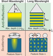
The inclusion of light-scattering effects in solar cells is a photonic strategy to increase the absorption for the lower-energy sunlight photons (chiefly in near-infrared range) for which the photovoltaic material presents reduced absorption coefficient. Such light-trapping scheme is accomplished by the deviation of the light rays from the incident direction, thereby increasing their path length in the cells' absorber.[38] Conventional approaches used to implement light diffusion are based on textured rear/front surfaces, but many alternative optical designs have been demonstrated with promising results based in diffraction gratings, arrays of metal or dielectric nano/micro particles, wave-optical micro-structuring, among others.[39] When applied in the devices' front these structures can act as geometric anti-reflective coatings, simultaneously reducing the reflection of out-going light.
For instance, lining the light-receiving surface of the cell with nano-sized metallic studs can substantially increase the cell efficiency. Light reflects off these studs at an oblique angle to the cell, increasing the length of the light path through the cell. This increases the number of photons absorbed by the cell and the amount of current generated.[40] The main materials used for the nano-studs are silver, gold, and aluminium. Gold and silver are not very efficient, as they absorb much of the light in the visible spectrum, which contains most of the energy present in sunlight, reducing the amount of light reaching the cell.[40] Aluminium absorbs only ultraviolet radiation, and reflects both visible and infra-red light, so energy loss is minimized. Aluminium can increase cell efficiency up to 22% (in lab conditions).[41]
Anti-reflective coatings and textures
Anti-reflective coatings are engineered to reduce the sunlight reflected from the solar cells, therefore enhancing the light transmitted into the photovoltaic absorber.[42] This can be accomplished by causing the destructive interference of the reflected light waves, such as with coatings based on the front (multi-)layer composition, and/or by geometric refractive-index matching caused by the surface topography, with many architectures inspired by nature.[43] For example, the nipple-array, a hexagonal array of subwavelength conical nanostructures, can be seen at the surface of the moth's eyes.[43] It was reported that utilizing this sort of surface architecture minimizes the reflection losses by 25%, converting the additional captured photon to a 12% increase in a solar cell's energy.[43]
The use of front micro-structures, such as those achieved with texturizing or other photonic features, can also be used as a method to achieve anti-reflectiveness, in which the surface of a solar cell is altered so that the impinging light experiences a gradually increasing effective refractive-index when travelling from air towards the photovoltaic material. These surfaces can be created by etching or using lithography. Concomitantly, they promote light scattering effects which further enhance the absorption, particularly of the longer wavelength sunlight photons.[37] Adding a flat back surface in addition to texturizing the front surface further helps to trap the light within the cell, thus providing a longer optical path.
Radiative cooling
An increase in solar cell temperature of approximately 1 °C causes an efficiency decrease of about 0.45%. To prevent this, a transparent silica crystal layer can be applied to solar panels. The silica layer acts as a thermal black body which emits heat as infrared radiation into space, cooling the cell up to 13 °C.[44] Radiative cooling can thus extend the life of solar cells.[45] Full-system integration of solar energy and radiative cooling is referred to as a combined SE–RC system, which have demonstrated higher energy gain per unit area when compared to non-integrated systems.[46]
Rear surface passivation
Surface passivation is critical to solar cell efficiency.[47] Many improvements have been made to the front side of mass-produced solar cells, but the aluminium back-surface is impeding efficiency improvements.[48] The efficiency of many solar cells has benefitted by creating so-called passivated emitter and rear cells (PERCs). The chemical deposition of a rear-surface dielectric passivation layer stack that is also made of a thin silica or aluminium oxide film topped with a silicon nitride film helps to improve efficiency in silicon solar cells. This helped increase cell efficiency for commercial Cz-Si wafer material from just over 17% to over 21% by the mid-2010s,[49] and the cell efficiency for quasi-mono-Si to a record 19.9%.
Concepts of the rear surface passivation for silicon solar cells has also been implemented for CIGS solar cells.[50] The rear surface passivation shows the potential to improve the efficiency. Al2O3 and SiO2 have been used as the passivation materials. Nano-sized point contacts on Al2O3 layer[51] and line contacts on SiO2 layer[52] provide the electrical connection of CIGS absorber to the rear electrode Molybdenum. The point contacts on the Al2O3 layer are created by e-beam lithography and the line contacts on the SiO2 layer are created using photolithography. Also, the implementation of the passivation layers does not change the morphology of the CIGS layers.

Thin film materials
Although not constituting a direct strategy to improve efficiency, thin film materials show a lot of promise for solar cells in terms of low costs and adaptability to existing structures and frameworks in technology.[53] Since the materials are so thin, they lack the optical absorption of bulk material solar cells. Attempts to correct this have been demonstrated, such as light-trapping schemes promoting light scattering.[54] Also important is thin film surface recombination. Since this is the dominant recombination process of nanoscale thin-film solar cells, it is crucial to their efficiency. Adding a passivating thin layer of silicon dioxide could reduce recombination.
Tandem cells
Tandem solar cells combine two materials to increase efficiency. In 2022 a device was announced that combined multiple perovskite with multiple layers of silicon. Perovskites demonstrate a remarkable ability to efficiently capture and convert blue light, complementing silicon, which is particularly adept at absorbing red and infrared wavelengths. This unique synergy between perovskites and silicon in solar cell technologies allows for a more comprehensive absorption of the solar spectrum, enhancing the overall efficiency and performance of photovoltaic devices. The cell achieved 32.5% efficiency.[55]
See also
References
- ^ a b Kannan, Nadarajah; Vakeesan, Divagar (1 September 2016). "Solar energy for future world: - A review". Renewable and Sustainable Energy Reviews. 62: 1092–1105. doi:10.1016/j.rser.2016.05.022. ISSN 1364-0321.
- ^ Köberle, Alexandre C.; Gernaat, David E. H. J.; van Vuuren, Detlef P. (1 September 2015). "Assessing current and future techno-economic potential of concentrated solar power and photovoltaic electricity generation". Energy. 89: 739–756. Bibcode:2015Ene....89..739K. doi:10.1016/j.energy.2015.05.145. hdl:1874/319865. ISSN 0360-5442. S2CID 108996432.
- ^ a b Billy Roberts (20 October 2008). "Photovoltaic Solar Resource of the United States". National Renewable Energy Laboratory. Retrieved 17 April 2017.
- ^ David J. C. MacKay. "Sustainable Energy - without the hot air". inference.org.uk. Retrieved 20 November 2017.
Solar photovoltaics: data from a 25-m2 array in Cambridgeshire in 2006
- ^ a b c Kumar, Ankush (3 January 2017). "Predicting efficiency of solar cells based on transparent conducting electrodes". Journal of Applied Physics. 121 (1): 014502. Bibcode:2017JAP...121a4502K. doi:10.1063/1.4973117. ISSN 0021-8979.
- ^ "Photovoltaic Cell Conversion Efficiency Basics". U.S. Department of Energy. Retrieved 6 September 2014.
- ^ Schygulla, Patrick; Beutel, Paul; Heckelmann, Stefan; Höhn, Oliver; Klitzke, Malte; Schön, Jonas; Oliva, Eduard; Predan, Felix; Schachtner, Michael; Siefer, Gerald; Helmers, Henning; Dimroth, Frank; Lackner, David (2022). Quadruple Junction Solar Cell with 47.6 % Conversion Efficiency under Concentration. International Conference on Metal Organic Vapor Phase Epitaxy 2022.
- ^ Geisz, John F.; France, Ryan M.; Schulte, Kevin L.; Steiner, Myles A.; Norman, Andrew G.; Guthrey, Harvey L.; Young, Matthew R.; Song, Tao; Moriarty, Thomas (April 2020). "Six-junction III–V solar cells with 47.1% conversion efficiency under 143 Suns concentration". Nature Energy. 5 (4): 326–335. Bibcode:2020NatEn...5..326G. doi:10.1038/s41560-020-0598-5. ISSN 2058-7546. OSTI 1659948. S2CID 216289881.
- ^ Ozdemir, Derya (20 May 2022). "Scientists just broke the record for the highest efficiency solar cell". interestingengineering.com. Retrieved 7 August 2023.
- ^ France, Ryan M.; Geisz, John F.; Song, Tao; Olavarria, Waldo; Young, Michelle; Kibbler, Alan; Steiner, Myles A. (18 May 2022). "Triple-junction solar cells with 39.5% terrestrial and 34.2% space efficiency enabled by thick quantum well superlattices". Joule. 6 (5): 1121–1135. arXiv:2203.15593. doi:10.1016/j.joule.2022.04.024. ISSN 2542-4351. S2CID 247778421.
- ^ Shockley William; Queisser Hans J (1961). "Detailed Balance Limit of Efficiency of p-n Junction Solar Cells". Journal of Applied Physics. 32 (3): 510–519. Bibcode:1961JAP....32..510S. doi:10.1063/1.1736034. Archived from the original on 23 February 2013.
- ^ De Vos, A. (1980). "Detailed balance limit of the efficiency of tandem solar cells". Journal of Physics D: Applied Physics. 13 (5): 839–846. Bibcode:1980JPhD...13..839D. doi:10.1088/0022-3727/13/5/018. S2CID 250782402.
- ^ A. De Vos & H. Pauwels (1981). "On the Thermodynamic Limit of Photovoltaic Energy Conversion". Appl. Phys. 25 (2): 119–125. Bibcode:1981ApPhy..25..119D. doi:10.1007/BF00901283. S2CID 119693148.
- ^ Rühle, Sven (8 February 2016). "Tabulated Values of the Shockley–Queisser Limit for Single Junction Solar Cells". Solar Energy. 130: 139–147. Bibcode:2016SoEn..130..139R. doi:10.1016/j.solener.2016.02.015.
- ^ Cheng-Hsiao Wu & Richard Williams (1983). "Limiting efficiencies for multiple energy-gap quantum devices". J. Appl. Phys. 54 (11): 6721. Bibcode:1983JAP....54.6721W. doi:10.1063/1.331859.
- ^ Verlinden, Pierre; Evrard, Olivier; Mazy, Emmanuel; Crahay, André (March 1992). "The surface texturization of solar cells: A new method using V-grooves with controllable sidewall angles". Solar Energy Materials and Solar Cells. 26 (1–2): 71–78. doi:10.1016/0927-0248(92)90126-A.
- ^ a b Kirchartz, Thomas; Rau, Uwe (2018). "What Makes a Good Solar Cell?". Advanced Energy Materials. 8 (28): 1703385. Bibcode:2018AdEnM...803385K. doi:10.1002/aenm.201703385. S2CID 103853300.
- ^ A. Molki (2010). "Dust affects solar-cell efficiency". Physics Education. 45 (5): 456–458. Bibcode:2010PhyEd..45..456M. doi:10.1088/0031-9120/45/5/F03. S2CID 250818645.
- ^ a b Kawamoto, Hiroyuki; Guo, Bing (1 February 2018). "Improvement of an electrostatic cleaning system for removal of dust from solar panels". Journal of Electrostatics. 91: 28–33. doi:10.1016/j.elstat.2017.12.002. ISSN 0304-3886.
- ^ "Part II – Photovoltaic Cell I-V Characterization Theory and LabVIEW Analysis Code". Part II – Photovoltaic Cell I-V Characterization Theory and LabVIEW Analysis Code - National Instruments, 10 May 2012, ni.com/white-paper/7230/en/.
- ^ Jenny Nelson (2003). The Physics of Solar Cells. Imperial College Press. ISBN 978-1-86094-340-9.
- ^ "Solar Junction Breaks Its Own CPV Conversion Efficiency Record". 18 December 2013. Retrieved 18 December 2013.
- ^ "Solar Cell Efficiency World Record Set By Sharp — 44.4%". 28 July 2013. Retrieved 28 July 2013.
- ^ Schultz, O.; Mette, A.; Preu, R.; Glunz, S. W. (2007). "Silicon Solar Cells with Screen-Printed Front Side Metallization Exceeding 19% Efficiency".
- ^ A. Richter; M. Hermle; S.W. Glunz (October 2013). "Reassessment of the limiting efficiency for crystalline silicon solar cells". IEEE Journal of Photovoltaics. 3 (4): 1184–1191. doi:10.1109/JPHOTOV.2013.2270351. S2CID 6013813.
- ^ K. Yoshikawa; H. Kawasaki & W. Yoshida (2017). "Silicon heterojunction solar cell with interdigitated back contacts for a photoconversion efficiency over 26%". Nature Energy. 2 (5): 17032. Bibcode:2017NatEn...217032Y. doi:10.1038/nenergy.2017.32. S2CID 114171665.
- ^ "New World Record Established for Conversion Efficiency in a Crystalline Silicon Solar Cell". 25 August 2017. Retrieved 15 March 2018.
- ^ a b c "What is the Energy Payback for PV?" (PDF). December 2004. Retrieved 20 December 2008.
- ^ M. Ito; K. Kato; K. Komoto; et al. (2008). "A comparative study on cost and life-cycle analysis for 100 MW very large-scale PV (VLS-PV) systems in deserts using m-Si, a-Si, CdTe, and CIS modules". Progress in Photovoltaics: Research and Applications. 16: 17–30. doi:10.1002/pip.770. S2CID 97914857.
- ^ "Net Energy Analysis For Sustainable Energy Production From Silicon Based Solar Cells" (PDF). Retrieved 13 September 2011.
- ^ Corkish, Richard (1997). "Can Solar Cells Ever Recapture the Energy Invested in their Manufacture?". Solar Progress. 18 (2): 16–17.
- ^ K. L. Chopra; P. D. Paulson & V. Dutta (2004). "Thin-film solar cells: An overview Progress in Photovoltaics". Research and Applications. 12 (23): 69–92. doi:10.1002/pip.541. S2CID 39250492.
- ^ Peng, Jinqing; Lu, Lin; Yang, Hongxing (2013). "Review on lifecycle assessment of energy payback and greenhouse gas emission of solar photovoltaic systems". Renewable and Sustainable Energy Reviews. 19: 255–274. doi:10.1016/j.rser.2012.11.035. hdl:10397/34975.
- ^ Bhandari, Khagendra P.; Jennifer, M.Collier; Ellingson, Randy J.; Apul, Defne S. (2015). "Energy payback time (EPBT) and energy return on energy invested (EROI) of solar photovoltaic systems: A systematic review and meta-analysis". Renewable and Sustainable Energy Reviews. 47: 133–141. doi:10.1016/j.rser.2015.02.057.
- ^ "Highest silicon solar cell efficiency ever reached". ScienceDaily. 24 October 2008. Retrieved 9 December 2009.
- ^ Trainer, FE (2007) "Renewable Energy Cannot Sustain a Consumer Society"
- ^ a b Mendes, Manuel J.; Araújo, Andreia; Vicente, António; Águas, Hugo; Ferreira, Isabel; Fortunato, Elvira; Martins, Rodrigo (1 August 2016). "Design of optimized wave-optical spheroidal nanostructures for photonic-enhanced solar cells". Nano Energy. 26: 286–296. doi:10.1016/j.nanoen.2016.05.038. ISSN 2211-2855.
- ^ Schuster, Christian Stefano; Crupi, Isodiana; Halme, Janne; Koç, Mehmet; Mendes, Manuel João; Peters, Ian Marius; Yerci, Selçuk (2022), Lackner, Maximilian; Sajjadi, Baharak; Chen, Wei-Yin (eds.), "Empowering Photovoltaics with Smart Light Management Technologies", Handbook of Climate Change Mitigation and Adaptation, Cham: Springer International Publishing, pp. 1165–1248, doi:10.1007/978-3-030-72579-2_112, ISBN 978-3-030-72579-2, retrieved 9 March 2023
- ^ Mendes, Manuel J.; Sanchez-Sobrado, Olalla; Haque, Sirazul; Mateus, Tiago; Águas, Hugo; Fortunato, Elvira; Martins, Rodrigo (1 January 2020), Enrichi, Francesco; Righini, Giancarlo C. (eds.), "Chapter Nine - Wave-optical front structures on silicon and perovskite thin-film solar cells", Solar Cells and Light Management, Elsevier, pp. 315–354, ISBN 978-0-08-102762-2, retrieved 9 March 2023
- ^ a b Mukunth, Vasudevan (24 October 2013). "Improving the efficiency of solar panels". The Hindu. Retrieved 6 August 2016.
- ^ Hylton, Nicholas; Li, X. F; Giannini, K. H.; Lee, N. J; Ekins-Daukes, N. J.; Loo, J.; Vercruysse, D.; Van Dorpe, P.; Sodabanlu, H.; Sugiyama, M.; Maier, S. A. (7 October 2013). "Loss mitigation in plasmonic solar cells: aluminium nanoparticles for broadband photocurrent enhancements in GaAs photodiodes". Scientific Reports. 3: 2874. Bibcode:2013NatSR...3E2874H. doi:10.1038/srep02874. PMC 3791440. PMID 24096686.
- ^ Gee, Justin. "How to Make Solar Panels More Efficient in 2018 | EnergySage". EnergySage Solar News Feed, EnergySage, 19 Sept. 2017, news.energysage.com/how-to-make-solar-panels-more-efficient/.
- ^ a b c Raut, Hemant Kumar; Ganesh, V. Anand; Nair, A. Sreekumaran; Ramakrishna, Seeram (2011). "Anti-reflective coatings: A critical, in-depth review". Energy & Environmental Science. 4 (10): 3779. doi:10.1039/c1ee01297e. ISSN 1754-5692.
- ^ Zhu, Linxiao; Raman, Aaswath P.; Fan, Shanhui (6 October 2015). "Radiative cooling of solar absorbers using a visibly transparent photonic crystal thermal blackbody". Proceedings of the National Academy of Sciences. 112 (40): 12282–12287. Bibcode:2015PNAS..11212282Z. doi:10.1073/pnas.1509453112. ISSN 0027-8424. PMC 4603484. PMID 26392542.
- ^ Heo, Se-Yeon; Ju Lee, Gil; Song, Young Min (June 2022). "Heat-shedding with photonic structures: radiative cooling and its potential". Journal of Materials Chemistry C. 10 (27): 9915–9937. doi:10.1039/D2TC00318J. S2CID 249695930 – via Royal Society of Chemistry.
- ^ Ahmed, Salman; Li, Zhenpeng; Javed, Muhammad Shahzad; Ma, Tao (September 2021). "A review on the integration of radiative cooling and solar energy harvesting". Materials Today: Energy. 21: 100776. doi:10.1016/j.mtener.2021.100776 – via Elsevier Science Direct.
- ^ Black, Lachlan E. (2016). New Perspectives on Surface Passivation: Understanding the Si-Al2O3 Interface (PDF). Springer. ISBN 9783319325217.
- ^ "Rear-Surface Passivation Technology for Crystalline Silicon Solar Cells: A Versatile Process for Mass Production". Ieee, IEEE, 2012, www.osapublishing.org/DirectPDFAccess/F1E0036E-C63D-5F6F-EA52FF38B5D1786D_270075/oe-21-S6-A1065.pdf?da=1&id=270075&seq=0&mobile=no.
- ^ Black, Lachlan E. (2016). New Perspectives on Surface Passivation: Understanding the Si-Al2O3 Interface (PDF). Springer. pp. 1–2. ISBN 9783319325217.
- ^ Vermang, Bart; Wätjen, Jörn Timo; Fjällström, Viktor; Rostvall, Fredrik; Edoff, Marika; Kotipalli, Ratan; Henry, Frederic; Flandre, Denis (2014). "Employing Si solar cell technology to increase efficiency of ultra-thin Cu(In, Ga)Se2 solar cells". Progress in Photovoltaics: Research and Applications. 22 (10): 1023–1029. doi:10.1002/pip.2527. PMC 4540152. PMID 26300619.
- ^ Bose, S.; Cunha, J.M.V.; Borme, J.; Chen, W.C.; Nilsson, N.S.; Teixeira, J.P.; Gaspar, J.; Leitão, J.P.; Edoff, M.; Fernandes, P.A.; Salomé, P.M.P. (2019). "A morphological and electronic study of ultrathin rear passivated Cu(In, Ga) Se2 solar cells". Thin Solid Films. 671: 77–84. Bibcode:2019TSF...671...77B. doi:10.1016/j.tsf.2018.12.028. hdl:10773/30445. S2CID 139582764.
- ^ Bose, Sourav; Cunha, José M. V.; Suresh, Sunil; De Wild, Jessica; Lopes, Tomás S.; Barbosa, João R. S.; Silva, Ricardo; Borme, Jérôme; Fernandes, Paulo A.; Vermang, Bart; Salomé, Pedro M. P. (2018). "Optical Lithography Patterning of SiO2 Layers for Interface Passivation of Thin Film Solar Cells". RRL Solar. 2 (12): 1800212. doi:10.1002/solr.201800212. hdl:10773/30564. S2CID 139388117.
- ^ Da, Yun, and Yimin Xuan. "Role of Surface Recombination in Affecting the Efficiency of Nanostructured Thin-Film Solar Cells .” Osapublishing, 2013, www.osapublishing.org/DirectPDFAccess/F1E0036E-C63D-5F6F-EA52FF38B5D1786D_270075/oe-21-S6-A1065
- ^ Mendes, Manuel J.; Haque, Sirazul; Sanchez-Sobrado, Olalla; Araújo, Andreia; Águas, Hugo; Fortunato, Elvira; Martins, Rodrigo (25 May 2018). "Optimal-Enhanced Solar Cell Ultra-thinning with Broadband Nanophotonic Light Capture". iScience. 3: 238–254. Bibcode:2018iSci....3..238M. doi:10.1016/j.isci.2018.04.018. ISSN 2589-0042. PMC 6137392. PMID 30428324.
- ^ Irving, Michael (20 December 2022). "Perovskite/silicon tandem solar cell advance breaks efficiency record". New Atlas. Retrieved 26 December 2022.
External links
- Solar electric at Curlie
- "How Can We Increase the Efficiency of Solar Panels?".
- "Factors That Affect Solar Panel Efficiency". 18 July 2021.
| Concepts |    | ||||||||||||||||
|---|---|---|---|---|---|---|---|---|---|---|---|---|---|---|---|---|---|
| Solar power |
| ||||||||||||||||
| Distribution and uses |
| ||||||||||||||||
| Applications |
| ||||||||||||||||
| See also | |||||||||||||||||