To install click the Add extension button. That's it.

The source code for the WIKI 2 extension is being checked by specialists of the Mozilla Foundation, Google, and Apple. You could also do it yourself at any point in time.

4,5
Kelly Slayton
Congratulations on this excellent venture… what a great idea!
Alexander Grigorievskiy
I use WIKI 2 every day and almost forgot how the original Wikipedia looks like.
Live Statistics
English Articles
Improved in 24 Hours
Added in 24 Hours
What we do. Every page goes through several hundred of perfecting techniques; in live mode. Quite the same Wikipedia. Just better.
.
Leo
Newton
Brights
Milds

File:Two slider crystal radio circuit.svg

From Wikipedia, the free encyclopedia

Original file(SVG file, nominally 382 × 417 pixels, file size: 18 KB)

Summary

Description
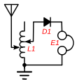
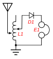
Circuit of a "two-slider" crystal radio receiver, a popular circuit used in simple crystal radios made before 1920. To tune in different stations, it used a tuning coil (L1) with two sliding contacts on it. It doesn't use a tuning capacitor, instead the coil resonates with the capacitance of the long wire antenna to create a tuned circuit. The left-hand slider tunes the receiver to different stations, allowing more or less of the coil's turns in parallel with the antenna capacitance. The right-hand slider adjusts the impedance match between the antenna and the rest of the circuit, to maximise the power transferred from the antenna into the receiver. It is adjusted until the station sounds loudest in the earphone (E1). The coil acts as an impedance matching transformer to match the low impedance (10-200 ohms) of the antenna-ground circuit with the higher impedance (thousands of ohms) of the coil at resonance. The two adjustments were interactive, so adjusting the right slider also detuned the radio, requiring retuning.
Date
Source Own work
Author Chetvorno
SVG development
InfoField
 
The SVG code is valid.
 
This diagram was created with Inkscape, or with something else.
 
This diagram uses translateable embedded text.

Licensing

I, Chetvorno, the author of this work, release it into the public domain for any use whatever

Public domain I, the copyright holder of this work, release this work into the public domain. This applies worldwide.
In some countries this may not be legally possible; if so:
I grant anyone the right to use this work for any purpose, without any conditions, unless such conditions are required by law.

Captions

Circuit of a crystal radio

Items portrayed in this file

depicts

20 May 2010

File history

Click on a date/time to view the file as it appeared at that time.

Date/TimeThumbnailDimensionsUserComment
current04:09, 9 May 2017Thumbnail for version as of 04:09, 9 May 2017382 × 417 (18 KB)ChetvornoReplaced with "plain SVG" version which passes validation
02:22, 28 January 2016Thumbnail for version as of 02:22, 28 January 2016382 × 417 (24 KB)ChetvornoIncreased line width and tweaked location of components
07:34, 20 May 2010Thumbnail for version as of 07:34, 20 May 2010384 × 424 (24 KB)Chetvorno{{Information |Description={{en|Circuit of a "two-slider" Wikipedia:crystal radio receiver, a common circuit used in simple crystal radios made before 1920. To tune in different stations, it used a tuning coil ''L1'' with two sliding contacts on it.
The following pages on the English Wikipedia use this file (pages on other projects are not listed):

Global file usage

The following other wikis use this file:

Metadata

Basis of this page is in Wikipedia. Text is available under the CC BY-SA 3.0 Unported License. Non-text media are available under their specified licenses. Wikipedia® is a registered trademark of the Wikimedia Foundation, Inc. WIKI 2 is an independent company and has no affiliation with Wikimedia Foundation.