To install click the Add extension button. That's it.

The source code for the WIKI 2 extension is being checked by specialists of the Mozilla Foundation, Google, and Apple. You could also do it yourself at any point in time.

4,5
Kelly Slayton
Congratulations on this excellent venture… what a great idea!
Alexander Grigorievskiy
I use WIKI 2 every day and almost forgot how the original Wikipedia looks like.
Live Statistics
English Articles
Improved in 24 Hours
Added in 24 Hours
What we do. Every page goes through several hundred of perfecting techniques; in live mode. Quite the same Wikipedia. Just better.
.
Leo
Newton
Brights
Milds

File:Common crystal radio circuit.svg

From Wikipedia, the free encyclopedia

Original file(SVG file, nominally 517 × 426 pixels, file size: 23 KB)

Summary

Description
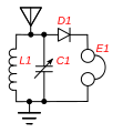
Common crystal radio circuit, used in inexpensive crystal radios sold today. The tuning coil L and capacitor C1 together make up the tuned circuit; it selects the radio signal to be received, out of all the signals picked up by the antenna. C1 is adjustable, and is used to tune in different stations. The crystal detector D rectifies the radio frequency current from the tuned circuit to pulsing direct current to extract the audio modulation from the radio frequency carrier wave. The earphone E converts the audio current to sound waves.
Date
Source Own work
Author Chetvorno
SVG development
InfoField
 
The SVG code is valid.
 
This diagram was created with Adobe Illustrator.

Licensing

Public domain This work has been released into the public domain by its author, Chetvorno. This applies worldwide.
In some countries this may not be legally possible; if so:
Chetvorno grants anyone the right to use this work for any purpose, without any conditions, unless such conditions are required by law.

Captions

A circuit diagram of a crystal radio

18 May 2010

image/svg+xml

ada3e4dcc3ae4579505cc717912fb11338aa5131

23,346 byte

426 pixel

517 pixel

File history

Click on a date/time to view the file as it appeared at that time.

Date/TimeThumbnailDimensionsUserComment
current20:03, 19 July 2018Thumbnail for version as of 20:03, 19 July 2018517 × 426 (23 KB)ChetvornoImproved placement of parts, simplified labels, added label for antenna
02:42, 28 January 2016Thumbnail for version as of 02:42, 28 January 2016517 × 426 (33 KB)ChetvornoIncreased line width and tweaked location of antenna and ground
21:54, 9 June 2010Thumbnail for version as of 21:54, 9 June 2010364 × 426 (28 KB)ChetvornoReplaced circuit diagram with identical one lacking blocking capacitor
04:30, 21 May 2010Thumbnail for version as of 04:30, 21 May 2010517 × 426 (34 KB)Chetvorno{{Information |Description={{en|Common Wikipedia:crystal radio circuit, used in educational crystal radios sold today. The tuned circuit ''L1'', ''C1'' is tuned to different stations by a variable capacitor. The crystal detector ''D1'' rectifies the
The following pages on the English Wikipedia use this file (pages on other projects are not listed):

Global file usage

The following other wikis use this file:

Metadata

Basis of this page is in Wikipedia. Text is available under the CC BY-SA 3.0 Unported License. Non-text media are available under their specified licenses. Wikipedia® is a registered trademark of the Wikimedia Foundation, Inc. WIKI 2 is an independent company and has no affiliation with Wikimedia Foundation.