

A waveguide filter is an electronic filter constructed with waveguide technology. Waveguides are hollow metal conduits inside which an electromagnetic wave may be transmitted. Filters are devices used to allow signals at some frequencies to pass (the passband), while others are rejected (the stopband). Filters are a basic component of electronic engineering designs and have numerous applications. These include selection of signals and limitation of noise. Waveguide filters are most useful in the microwave band of frequencies, where they are a convenient size and have low loss. Examples of microwave filter use are found in satellite communications, telephone networks, and television broadcasting.
Waveguide filters were developed during World War II to meet the needs of radar and electronic countermeasures, but afterwards soon found civilian applications such as use in microwave links. Much of post-war development was concerned with reducing the bulk and weight of these filters, first by using new analysis techniques that led to elimination of unnecessary components, then by innovations such as dual-mode cavities and novel materials such as ceramic resonators.
A particular feature of waveguide filter design concerns the mode of transmission. Systems based on pairs of conducting wires and similar technologies have only one mode of transmission. In waveguide systems, any number of modes are possible. This can be both a disadvantage, as spurious modes frequently cause problems, and an advantage, as a dual-mode design can be much smaller than the equivalent waveguide single mode design. The chief advantages of waveguide filters over other technologies are their ability to handle high power and their low loss. The chief disadvantages are their bulk and cost when compared with technologies such as microstrip filters.
There is a wide array of different types of waveguide filters. Many of them consist of a chain of coupled resonators of some kind that can be modelled as a ladder network of LC circuits. One of the most common types consists of a number of coupled resonant cavities. Even within this type, there are many subtypes, mostly differentiated by the means of coupling. These coupling types include apertures,[w] irises,[x] and posts. Other waveguide filter types include dielectric resonator filters, insert filters, finline filters, corrugated-waveguide filters, and stub filters. A number of waveguide components have filter theory applied to their design, but their purpose is something other than to filter signals. Such devices include impedance matching components, directional couplers, and diplexers. These devices frequently take on the form of a filter, at least in part.
YouTube Encyclopedic
-
1/5Views:5 06572 766252 2223 734482
-
10GHz Amateur TV Transmitter using Gunn Diode.
-
145 MHz Low Loss Bandpass Helical Filter by Mile Kokotov
-
Transmission Lines - Signal Transmission and Reflection
-
$10 Amateur TV With 10ghz HB100 Radar Module
-
NG7M - KF7P Metalwerks Junction Box / Entry Panel - Installation
Transcription
Scope
The common meaning of waveguide, when the term is used unqualified, is the hollow metal kind (or occasionally dielectric filled), but other waveguide technologies are possible.[1] The scope of this article is limited to the metal-conduit type. The post-wall waveguide structure is something of a variant, but is related enough to include in this article—the wave is mostly surrounded by conducting material. It is possible to construct waveguides out of dielectric rods,[2] the most well known example being optical fibres. This subject is outside the scope of the article with the exception that dielectric rod resonators are sometimes used inside hollow metal waveguides. Transmission line[o] technologies such as conducting wires and microstrip can be thought of as waveguides,[3] but are not commonly called such and are also outside the scope of this article.
Basic concepts
Filters
In electronics, filters are used to allow signals of a certain band of frequencies to pass while blocking others. They are a basic building block of electronic systems and have a great many applications. Amongst the uses of waveguide filters are the construction of duplexers, diplexers,[d] and multiplexers; selectivity and noise limitation in receivers; and harmonic distortion suppression in transmitters.[4]
Waveguides
Waveguides are metal conduits used to confine and direct radio signals. They are usually made of brass, but aluminium and copper are also used.[5] Most commonly they are rectangular, but other cross-sections such as circular or elliptical are possible. A waveguide filter is a filter composed of waveguide components. It has much the same range of applications as other filter technologies in electronics and radio engineering but is very different mechanically and in principle of operation.[6]
The technology used for constructing filters is chosen to a large extent by the frequency of operation that is expected, although there is a large amount of overlap. Low frequency applications such as audio electronics use filters composed of discrete capacitors and inductors. Somewhere in the very high frequency band, designers switch to using components made of pieces of transmission line.[p] These kinds of designs are called distributed element filters. Filters made from discrete components are sometimes called lumped element filters to distinguish them. At still higher frequencies, the microwave bands, the design switches to waveguide filters, or sometimes a combination of waveguides and transmission lines.[7]
Waveguide filters have much more in common with transmission line filters than lumped element filters; they do not contain any discrete capacitors or inductors. However, the waveguide design may frequently be equivalent (or approximately so) to a lumped element design. Indeed, the design of waveguide filters frequently starts from a lumped element design and then converts the elements of that design into waveguide components.[8]
Modes

One of the most important differences in the operation of waveguide filters compared to transmission line designs concerns the mode of transmission of the electromagnetic wave carrying the signal. In a transmission line, the wave is associated with electric currents on a pair of conductors. The conductors constrain the currents to be parallel to the line, and consequently both the magnetic and electric components of the electromagnetic field are perpendicular to the direction of travel of the wave. This transverse mode is designated TEM[l] (transverse electromagnetic). On the other hand, there are infinitely many modes that any completely hollow waveguide can support, but the TEM mode is not one of them. Waveguide modes are designated either TE[m] (transverse electric) or TM[n] (transverse magnetic), followed by a pair of suffixes identifying the precise mode.[9]
This multiplicity of modes can cause problems in waveguide filters when spurious modes are generated. Designs are usually based on a single mode and frequently incorporate features to suppress the unwanted modes. On the other hand, advantage can be had from choosing the right mode for the application, and even sometimes making use of more than one mode at once. Where only a single mode is in use, the waveguide can be modelled like a conducting transmission line and results from transmission line theory can be applied.[10]
Cutoff
Another feature peculiar to waveguide filters is that there is a definite frequency, the cutoff frequency, below which no transmission can take place. This means that in theory low-pass filters cannot be made in waveguides. However, designers frequently take a lumped element low-pass filter design and convert it to a waveguide implementation. The filter is consequently low-pass by design and may be considered a low-pass filter for all practical purposes if the cutoff frequency is below any frequency of interest to the application. The waveguide cutoff frequency is a function of transmission mode, so at a given frequency, the waveguide may be usable in some modes but not others. Likewise, the guide wavelength[h] (λg) and characteristic impedance[b] (Z0) of the guide at a given frequency also depend on mode.[11]
Dominant mode
The mode with the lowest cutoff frequency of all the modes is called the dominant mode. Between cutoff and the next highest mode, this is the only mode it is possible to transmit, which is why it is described as dominant. Any spurious modes generated are rapidly attenuated along the length of the guide and soon disappear. Practical filter designs are frequently made to operate in the dominant mode.[12]
In rectangular waveguide, the TE10[q] mode (shown in figure 2) is the dominant mode. There is a band of frequencies between the dominant mode cutoff and the next highest mode cutoff in which the waveguide can be operated without any possibility of generating spurious modes. The next highest cutoff modes are TE20,[r] at exactly twice the TE10 mode, and TE01[s] which is also twice TE10 if the waveguide used has the commonly used aspect ratio of 2:1. The lowest cutoff TM mode is TM11[t] (shown in figure 2) which is times the dominant mode in 2:1 waveguide. Thus, there is an octave over which the dominant mode is free of spurious modes, although operating too close to cutoff is usually avoided because of phase distortion.[13]

In circular waveguide, the dominant mode is TE11[u] and is shown in figure 2. The next highest mode is TM01.[v] The range over which the dominant mode is guaranteed to be spurious-mode free is less than that in rectangular waveguide; the ratio of highest to lowest frequency is approximately 1.3 in circular waveguide, compared to 2.0 in rectangular guide.[14]
Evanescent modes
Evanescent modes are modes below the cutoff frequency. They cannot propagate down the waveguide for any distance, dying away exponentially. However, they are important in the functioning of certain filter components such as irises and posts, described later, because energy is stored in the evanescent wave fields.[15]
Advantages and disadvantages
Like transmission line filters, waveguide filters always have multiple passbands, replicas of the lumped element prototype. In most designs, only the lowest frequency passband is useful (or lowest two in the case of band-stop filters) and the rest are considered unwanted spurious artefacts. This is an intrinsic property of the technology and cannot be designed out, although design can have some control over the frequency position of the spurious bands. Consequently, in any given filter design, there is an upper frequency beyond which the filter will fail to carry out its function. For this reason, true low-pass and high-pass filters cannot exist in waveguide. At some high frequency there will be a spurious passband or stopband interrupting the intended function of the filter. But, similar to the situation with waveguide cutoff frequency, the filter can be designed so that the edge of the first spurious band is well above any frequency of interest.[16]
The range of frequencies over which waveguide filters are useful is largely determined by the waveguide size needed. At lower frequencies the waveguide needs to be impractically large in order to keep the cutoff frequency below the operational frequency. On the other hand, filters whose operating frequencies are so high that the wavelengths are sub-millimetre cannot be manufactured with normal machine shop processes. At frequencies this high, fibre-optic technology starts to become an option.[17]
Waveguides are a low-loss medium. Losses in waveguides mostly come from ohmic dissipation caused by currents induced in the waveguide walls. Rectangular waveguide has lower loss than circular waveguide and is usually the preferred format, but the TE01 circular mode is very low loss and has applications in long-distance communications. Losses can be reduced by polishing the internal surfaces of the waveguide walls. In some applications which require rigorous filtering, the walls are plated with a thin layer of gold or silver to improve surface conductivity. An example of such requirements is satellite applications which require low loss, high selectivity, and linear group delay from their filters.[18]
One of the main advantages of waveguide filters over TEM mode technologies is the quality of their resonators. Resonator quality is characterised by a parameter called Q factor, or just Q. The Q of waveguide resonators is in the thousands, orders of magnitude higher than TEM mode resonators.[19] The resistance of conductors, especially in wound inductors, limits the Q of TEM resonators. This improved Q leads to better performing filters in waveguides, with greater stop band rejection. The limitation to Q in waveguides comes mostly from the ohmic losses in the walls described earlier, but silver plating the internal walls can more than double Q.[20]
Waveguides have good power handling capability, which leads to filter applications in radar.[21] Despite the performance advantages of waveguide filters, microstrip is often the preferred technology due to its low cost. This is especially true for consumer items and the lower microwave frequencies. Microstrip circuits can be manufactured by cheap printed circuit technology, and when integrated on the same printed board as other circuit blocks they incur little additional cost.[22]
History

The idea of a waveguide for electromagnetic waves was first suggested by Lord Rayleigh in 1897. Rayleigh proposed that a coaxial transmission line could have the centre conductor removed, and waves would still propagate down the inside of the remaining cylindrical conductor despite there no longer being a complete electrical circuit of conductors. He described this in terms of the wave reflecting repeatedly off the internal wall of the outer conductor in a zig-zag fashion as it progressed down the waveguide. Rayleigh was also the first to realise that there was a critical wavelength, the cutoff wavelength, proportional to the cylinder diameter, above which wave propagation is not possible. However, interest in waveguides waned because lower frequencies were more suitable for long-distance radio communication. Rayleigh's results were forgotten for a time and had to be rediscovered by others in the 1930s when interest in microwaves revived. Waveguides were first developed, in a circular form, by George Clark Southworth and J. F. Hargreaves in 1932.[23]
The first analogue filter design which went beyond a simple single resonator was created by George Ashley Campbell in 1910 and marked the beginning of filter theory. Campbell's filter was a lumped-element design of capacitors and inductors suggested by his work with loading coils. Otto Zobel and others quickly developed this further.[24] Development of distributed element filters began in the years before World War II. A major paper on the subject was published by Mason and Sykes in 1937;[25] a patent[26] filed by Mason in 1927 may contain the first published filter design using distributed elements.[27]

Mason and Sykes' work was focused on the formats of coaxial cable and balanced pairs of wires, but other researchers later applied the principles to waveguides as well. Much development on waveguide filters was carried out during World War II driven by the filtering needs of radar and electronic countermeasures. A good deal of this was at the MIT Radiation Laboratory (Rad Lab), but other laboratories in the US and the UK were also involved such as the Telecommunications Research Establishment in the UK. Amongst the well-known scientists and engineers at Rad Lab were Julian Schwinger, Nathan Marcuvitz, Edward Mills Purcell, and Hans Bethe. Bethe was only at Rad Lab a short time but produced his aperture theory while there. Aperture theory is important for waveguide cavity filters, which were first developed at Rad Lab. Their work was published after the war in 1948 and includes an early description of dual-mode cavities by Fano and Lawson.[28]
Theoretical work following the war included the commensurate line theory of Paul Richards. Commensurate lines are networks in which all the elements are the same length (or in some cases multiples of the unit length), although they may differ in other dimensions to give different characteristic impedances.[a] Richards' transformation allows any lumped element design to be taken "as is" and transformed directly into a distributed element design using a very simple transform equation. In 1955 K. Kuroda published the transformations known as Kuroda's identities. These made Richard's work more usable in unbalanced and waveguide formats by eliminating the problematic series connected elements, but it was some time before Kuroda's Japanese work became widely known in the English speaking world.[29] Another theoretical development was the network synthesis filter approach of Wilhelm Cauer in which he used the Chebyshev approximation to determine element values. Cauer's work was largely developed during World War II (Cauer was killed towards the end of it), but could not be widely published until hostilities ended. While Cauer's work concerns lumped elements, it is of some importance to waveguide filters; the Chebyshev filter, a special case of Cauer's synthesis, is widely used as a prototype filter for waveguide designs.[30]
Designs in the 1950s started with a lumped element prototype (a technique still in use today), arriving after various transformations at the desired filter in a waveguide form. At the time, this approach was yielding fractional bandwidths no more than about 1/5. In 1957, Leo Young at Stanford Research Institute published a method for designing filters which started with a distributed element prototype, the stepped impedance prototype. This filter was based on quarter-wave impedance transformers of various widths and was able to produce designs with bandwidths up to an octave (a fractional bandwidth of 2/3). Young's paper specifically addresses directly coupled cavity resonators, but the procedure can equally be applied to other directly coupled resonator types.[31]

The first published account of a cross-coupled filter is due to John R. Pierce at Bell Labs in a 1948 patent.[32] A cross-coupled filter is one in which resonators that are not immediately adjacent are coupled. The additional degrees of freedom thus provided allow the designer to create filters with improved performance, or, alternatively, with fewer resonators. One version of Pierce's filter, shown in figure 3, uses circular waveguide cavity resonators to link between rectangular guide cavity resonators. This principle was not at first much used by waveguide filter designers, but it was used extensively by mechanical filter designers in the 1960s, particularly R. A. Johnson at Collins Radio Company.[33]
The initial non-military application of waveguide filters was in the microwave links used by telecommunications companies to provide the backbone of their networks. These links were also used by other industries with large, fixed networks, notably television broadcasters. Such applications were part of large capital investment programs. They are now also used in satellite communications systems.[34]
The need for frequency-independent delay in satellite applications led to more research into the waveguide incarnation of cross-coupled filters. Previously, satellite communications systems used a separate component for delay equalisation. The additional degrees of freedom obtained from cross-coupled filters held out the possibility of designing a flat delay into a filter without compromising other performance parameters. A component that simultaneously functioned as both filter and equaliser would save valuable weight and space. The needs of satellite communication also drove research into the more exotic resonator modes in the 1970s. Of particular prominence in this respect is the work of E. L. Griffin and F. A. Young, who investigated better modes for the 12-14 GHz band when this began to be used for satellites in the mid-1970s.[35]
Another space-saving innovation was the dielectric resonator, which can be used in other filter formats as well as waveguide. The first use of these in a filter was by S. B. Cohn in 1965, using titanium dioxide as the dielectric material. Dielectric resonators used in the 1960s, however, had very poor temperature coefficients, typically 500 times worse than a mechanical resonator made of invar, which led to instability of filter parameters. Dielectric materials of the time with better temperature coefficients had too low a dielectric constant to be useful for space saving. This changed with the introduction of ceramic resonators with very low temperature coefficients in the 1970s. The first of these was from Massé and Pucel using barium tetratitanate[note 1] at Raytheon in 1972. Further improvements were reported in 1979 by Bell Labs and Murata Manufacturing. Bell Labs' barium nonatitanate[note 2] resonator had a dielectric constant of 40 and Q of 5000–10,000 at 2-7 GHz. Modern temperature-stable materials have a dielectric constant of about 90 at microwave frequencies, but research is continuing to find materials with both low loss and high permittivity; lower permittivity materials, such as zirconium stannate titanate[note 3] (ZST) with a dielectric constant of 38, are still sometimes used for their low loss property.[36]
An alternative approach to designing smaller waveguide filters was provided by the use of non-propagating evanescent modes. Jaynes and Edson proposed evanescent mode waveguide filters in the late 1950s. Methods for designing these filters were created by Craven and Young in 1966. Since then, evanescent mode waveguide filters have seen successful use where waveguide size or weight are important considerations.[37]
A relatively recent technology being used inside hollow-metal-waveguide filters is finline, a kind of planar dielectric waveguide. Finline was first described by Paul Meier in 1972.[38]
Multiplexer history

Multiplexers were first described by Fano and Lawson in 1948. Pierce was the first to describe multiplexers with contiguous passbands. Multiplexing using directional filters was invented by Seymour Cohn and Frank Coale in the 1950s. Multiplexers with compensating immittance resonators at each junction are largely the work of E. G. Cristal and G. L. Matthaei in the 1960s. This technique is still sometimes used, but the modern availability of computing power has led to the more common use of synthesis techniques which can directly produce matching filters without the need for these additional resonators. In 1965 R. J. Wenzel discovered that filters which were singly terminated,[k] rather than the usual doubly terminated, were complementary—exactly what was needed for a diplexer.[c] Wenzel was inspired by the lectures of circuit theorist Ernst Guillemin.[39]
Multi-channel, multi-octave multiplexers were investigated by Harold Schumacher at Microphase Corporation, and his results were published in 1976. The principle that multiplexer filters may be matched when joined together by modifying the first few elements, thus doing away with the compensating resonators, was discovered accidentally by E. J. Curly around 1968 when he mistuned a diplexer. A formal theory for this was provided by J. D. Rhodes in 1976 and generalised to multiplexers by Rhodes and Ralph Levy in 1979.[40]
From the 1980s, planar technologies, especially microstrip, have tended to replace other technologies used for constructing filters and multiplexers, especially in products aimed at the consumer market. The recent innovation of post-wall waveguide allows waveguide designs to be implemented on a flat substrate with low-cost manufacturing techniques similar to those used for microstrip.[41]
Components

Waveguide filter designs frequently consist of two different components repeated a number of times. Typically, one component is a resonator or discontinuity with a lumped circuit equivalent of an inductor, capacitor, or LC resonant circuit. Often, the filter type will take its name from the style of this component. These components are spaced apart by a second component, a length of guide which acts as an impedance transformer. The impedance transformers have the effect of making alternate instances of the first component appear to be a different impedance. The net result is a lumped element equivalent circuit of a ladder network. Lumped element filters are commonly ladder topology, and such a circuit is a typical starting point for waveguide filter designs. Figure 4 shows such a ladder. Typically, waveguide components are resonators, and the equivalent circuit would be LC resonators instead of the capacitors and inductors shown, but circuits like figure 4 are still used as prototype filters with the use of a band-pass or band-stop transformation.[42]
Filter performance parameters, such as stopband rejection and rate of transition between passband and stopband, are improved by adding more components and thus increasing the length of the filter. Where the components are repeated identically, the filter is an image parameter filter design, and performance is enhanced simply by adding more identical elements. This approach is typically used in filter designs which use a large number of closely spaced elements such as the waffle-iron filter. For designs where the elements are more widely spaced, better results can be obtained using a network synthesis filter design, such as the common Chebyshev filter and Butterworth filters. In this approach the circuit elements do not all have the same value, and consequently the components are not all the same dimensions. Furthermore, if the design is enhanced by adding more components then all the element values must be calculated again from scratch. In general, there will be no common values between the two instances of the design. Chebyshev waveguide filters are used where the filtering requirements are rigorous, such as satellite applications.[43][44]
Impedance transformer
An impedance transformer is a device which makes an impedance at its output port appear as a different impedance at its input port. In waveguide, this device is simply a short length of waveguide. Especially useful is the quarter-wave impedance transformer which has a length of λg/4. This device can turn capacitances into inductances and vice versa.[45] It also has the useful property of turning shunt-connected elements into series-connected elements and vice versa. Series-connected elements are otherwise difficult to implement in waveguide.[46]
Reflections and discontinuities
Many waveguide filter components work by introducing a sudden change, a discontinuity, to the transmission properties of the waveguide. Such discontinuities are equivalent to lumped impedance elements placed at that point. This arises in the following way: the discontinuity causes a partial reflection of the transmitted wave back down the guide in the opposite direction, the ratio of the two being known as the reflection coefficient. This is entirely analogous to a reflection on a transmission line where there is an established relationship between reflection coefficient and the impedance that caused the reflection. This impedance must be reactive, that is, it must be a capacitance or an inductance. It cannot be a resistance since no energy has been absorbed—it is all either transmitted onward or reflected. Examples of components with this function include irises, stubs, and posts, all described later in this article under the filter types in which they occur.[47]
Impedance step
An impedance step is an example of a device introducing a discontinuity. It is achieved by a step change in the physical dimensions of the waveguide. This results in a step change in the characteristic impedance of the waveguide. The step can be in either the E-plane[f] (change of height[j]) or the H-plane[g] (change of width[i]) of the waveguide.[48]
Resonant cavity filter
Cavity resonator
A basic component of waveguide filters is the cavity resonator. This consists of a short length of waveguide blocked at both ends. Waves trapped inside the resonator are reflected back and forth between the two ends. A given geometry of cavity will resonate at a characteristic frequency. The resonance effect can be used to selectively pass certain frequencies. Their use in a filter structure requires that some of the wave is allowed to pass out of one cavity into another through a coupling structure. However, if the opening in the resonator is kept small then a valid design approach is to design the cavity as if it were completely closed and errors will be minimal. A number of different coupling mechanisms are used in different classes of filter.[49]
The nomenclature for modes in a cavity introduces a third index, for example TE011. The first two indices describe the wave travelling up and down the length of the cavity, that is, they are the transverse mode numbers as for modes in a waveguide. The third index describes the longitudinal mode caused by the interference pattern of the forward travelling and reflected waves. The third index is equal to the number of half wavelengths down the length of the guide. The most common modes used are the dominant modes: TE101 in rectangular waveguide, and TE111 in circular waveguide. TE011 circular mode is used where very low loss (hence high Q) is required but cannot be used in a dual-mode filter because it is circularly symmetric. Better modes for rectangular waveguide in dual-mode filters are TE103 and TE105. However, even better is the TE113 circular waveguide mode which can achieve a Q of 16,000 at 12 GHz.[50]
Tuning screw
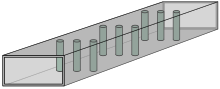
Tuning screws are screws inserted into resonant cavities which can be adjusted externally to the waveguide. They provide fine tuning of the resonant frequency by inserting more, or less thread into the waveguide. Examples can be seen in the post filter of figure 1: each cavity has a tuning screw secured with jam nuts and thread-locking compound. For screws inserted only a small distance, the equivalent circuit is a shunt capacitor, increasing in value as the screw is inserted. However, when the screw has been inserted a distance λ/4 it resonates equivalent to a series LC circuit. Inserting it further causes the impedance to change from capacitive to inductive, that is, the arithmetic sign changes.[51]
Iris

An iris is a thin metal plate across the waveguide with one or more holes in it. It is used to couple together two lengths of waveguide and is a means of introducing a discontinuity. Some of the possible geometries of irises are shown in figure 5. An iris which reduces the width of a rectangular waveguide has an equivalent circuit of a shunt inductance, whereas one which restricts the height is equivalent to a shunt capacitance. An iris which restricts both directions is equivalent to a parallel LC resonant circuit. A series LC circuit can be formed by spacing the conducting portion of the iris away from the walls of the waveguide. Narrowband filters frequently use irises with small holes. These are always inductive regardless of the shape of the hole or its position on the iris. Circular holes are simple to machine, but elongated holes, or holes in the shape of a cross, are advantageous in allowing the selection of a particular mode of coupling.[52]
Irises are a form of discontinuity and work by exciting evanescent higher modes. Vertical edges are parallel to the electric field (E field) and excite TE modes. The stored energy in TE modes is predominately in the magnetic field (H field), and consequently the lumped equivalent of this structure is an inductor. Horizontal edges are parallel to the H field and excite TM modes. In this case the stored energy is predominately in the E field and the lumped equivalent is a capacitor.[53]
It is fairly simple to make irises that are mechanically adjustable. A thin plate of metal can be pushed in and out of a narrow slot in the side of the waveguide. The iris construction is sometimes chosen for this ability to make a variable component.[54]
Iris-coupled filter

An iris-coupled filter consists of a cascade of impedance transformers in the form of waveguide resonant cavities coupled together by irises.[43] In high power applications capacitive irises are avoided. The reduction in height of the waveguide (the direction of the E field) causes the electric field strength across the gap to increase and arcing (or dielectric breakdown if the waveguide is filled with an insulator) will occur at a lower power than it would otherwise.[55]
Post filter
Posts are conducting bars, usually circular, fixed internally across the height of the waveguide and are another means of introducing a discontinuity. A thin post has an equivalent circuit of a shunt inductor. A row of posts can be viewed as a form of inductive iris.[56]
A post filter consists of several rows of posts across the width of the waveguide which separate the waveguide into resonant cavities as shown in figure 7. Differing numbers of posts can be used in each row to achieve varying values of inductance. An example can be seen in figure 1. The filter operates in the same way as the iris-coupled filter but differs in the method of construction.[57]
Post-wall waveguide
A post-wall waveguide, or substrate integrated waveguide, is a more recent format that seeks to combine the advantages of low radiation loss, high Q, and high power handling of traditional hollow metal pipe waveguide with the small size and ease of manufacture of planar technologies (such as the widely used microstrip format). It consists of an insulated substrate pierced with two rows of conducting posts which stand in for the side walls of the waveguide. The top and bottom of the substrate are covered with conducting sheets making this a similar construction to the triplate format. The existing manufacturing techniques of printed circuit board or low temperature co-fired ceramic can be used to make post-wall waveguide circuits. This format naturally lends itself to waveguide post filter designs.[58]
Dual-mode filter
A dual-mode filter is a kind of resonant cavity filter, but in this case each cavity is used to provide two resonators by employing two modes (two polarizations), so halving the volume of the filter for a given order. This improvement in size of the filter is a major advantage in aircraft avionics and space applications. High quality filters in these applications can require many cavities which occupy significant space.[59]
Dielectric resonator filter

Dielectric resonators are pieces of dielectric material inserted into the waveguide. They are usually cylindrical since these can be made without machining but other shapes have been used. They can be made with a hole through the centre which is used to secure them to the waveguide. There is no field at the centre when the TE011 circular mode is used so the hole has no adverse effect. The resonators can be mounted coaxial to the waveguide, but usually they are mounted transversally across the width as shown in figure 8. The latter arrangement allows the resonators to be tuned by inserting a screw through the wall of the waveguide into the centre hole of the resonator.[60]
When dielectric resonators are made from a high permittivity material, such as one of the barium titanates, they have an important space saving advantage compared to cavity resonators. However, they are much more prone to spurious modes. In high-power applications, metal layers may be built into the resonators to conduct heat away since dielectric materials tend to have low thermal conductivity.[61]
The resonators can be coupled together with irises or impedance transformers. Alternatively, they can be placed in a stub-like side-housing and coupled through a small aperture.[62]
Insert filter

In insert filters one or more metal sheets are placed longitudinally down the length of the waveguide as shown in figure 9. These sheets have holes punched in them to form resonators. The air dielectric gives these resonators a high Q. Several parallel inserts may be used in the same length of waveguide. More compact resonators may be achieved with a thin sheet of dielectric material and printed metallisation instead of holes in metal sheets at the cost of a lower resonator Q.[63]
Finline filter
Finline is a different kind of waveguide technology in which waves in a thin strip of dielectric are constrained by two strips of metallisation. There are a number of possible topological arrangements of the dielectric and metal strips. Finline is a variation of slot-waveguide but in the case of finline the whole structure is enclosed in a metal shield. This has the advantage that, like hollow metal waveguide, no power is lost by radiation. Finline filters can be made by printing a metallisation pattern on to a sheet of dielectric material and then inserting the sheet into the E-plane of a hollow metal waveguide much as is done with insert filters. The metal waveguide forms the shield for the finline waveguide. Resonators are formed by metallising a pattern on to the dielectric sheet. More complex patterns than the simple insert filter of figure 9 are easily achieved because the designer does not have to consider the effect on mechanical support of removing metal. This complexity does not add to the manufacturing costs since the number of processes needed does not change when more elements are added to the design. Finline designs are less sensitive to manufacturing tolerances than insert filters and have wide bandwidths.[64]
Evanescent-mode filter
It is possible to design filters that operate internally entirely in evanescent modes. This has space saving advantages because the filter waveguide, which often forms the housing of the filter, does not need to be large enough to support propagation of the dominant mode. Typically, an evanescent mode filter consists of a length of waveguide smaller than the waveguide feeding the input and output ports. In some designs this may be folded to achieve a more compact filter. Tuning screws are inserted at specific intervals along the waveguide producing equivalent lumped capacitances at those points. In more recent designs the screws are replaced with dielectric inserts. These capacitors resonate with the preceding length of evanescent mode waveguide which has the equivalent circuit of an inductor, thus producing a filtering action. Energy from many different evanescent modes is stored in the field around each of these capacitive discontinuities. However, the design is such that only the dominant mode reaches the output port; the other modes decay much more rapidly between the capacitors.[65]
Corrugated-waveguide filter


Corrugated-waveguide filters, also called ridged-waveguide filters, consist of a number of ridges, or teeth, that periodically reduce the internal height of the waveguide as shown in figures 10 and 11. They are used in applications which simultaneously require a wide passband, good passband matching, and a wide stopband. They are essentially low-pass designs (above the usual limitation of the cutoff frequency), unlike most other forms which are usually band-pass. The distance between teeth is much smaller than the typical λ/4 distance between elements of other filter designs. Typically, they are designed by the image parameter method with all ridges identical, but other classes of filter such as Chebyshev can be achieved in exchange for complexity of manufacture. In the image design method the equivalent circuit of the ridges is modelled as a cascade of LC half sections. The filter operates in the dominant TE10 mode, but spurious modes can be a problem when they are present. In particular, there is little stopband attenuation of TE20 and TE30 modes.[66]
Waffle-iron filter
The waffle-iron filter is a variant of the corrugated-waveguide filter. It has similar properties to that filter with the additional advantage that spurious TE20 and TE30 modes are suppressed. In the waffle-iron filter, channels are cut through the ridges longitudinally down the filter. This leaves a matrix of teeth protruding internally from the top and bottom surfaces of the waveguide. This pattern of teeth resembles a waffle iron, hence the name of the filter.[67]
Waveguide stub filter

A stub is a short length of waveguide connected to some point in the filter at one end and short-circuited at the other end. Open-circuited stubs are also theoretically possible, but an implementation in waveguide is not practical because electromagnetic energy would be emitted from the open end of the stub, resulting in high losses. Stubs are a kind of resonator, and the lumped element equivalent is an LC resonant circuit. However, over a narrow band, stubs can be viewed as an impedance transformer. The short-circuit is transformed into either an inductance or a capacitance depending on the stub length.[68]
A waveguide stub filter is made by placing one or more stubs along the length of a waveguide, usually λg/4 apart, as shown in figure 12. The ends of the stubs are blanked off to short-circuit them.[69] When the short-circuited stubs are λg/4 long the filter will be a band-stop filter and the stubs will have a lumped-element approximate equivalent circuit of parallel resonant circuits connected in series with the line. When the stubs are λg/2 long, the filter will be a band-pass filter. In this case the lumped-element equivalent is series LC resonant circuits in series with the line.[70]
Absorption filter
Absorption filters dissipate the energy in unwanted frequencies internally as heat. This is in contrast to a conventional filter design where the unwanted frequencies are reflected back from the input port of the filter. Such filters are used where it is undesirable for power to be sent back towards the source. This is the case with high power transmitters where returning power can be high enough to damage the transmitter. An absorption filter may be used to remove transmitter spurious emissions such as harmonics or spurious sidebands. A design that has been in use for some time has slots cut in the walls of the feed waveguide at regular intervals. This design is known as a leaky-wave filter. Each slot is connected to a smaller gauge waveguide which is too small to support propagation of frequencies in the wanted band. Thus those frequencies are unaffected by the filter. Higher frequencies in the unwanted band, however, readily propagate along the side guides which are terminated with a matched load where the power is absorbed. These loads are usually a wedge shaped piece of microwave absorbent material.[71] Another, more compact, design of absorption filter uses resonators with a lossy dielectric.[72]
Filter-like devices
There are many applications of filters whose design objectives are something other than rejection or passing of certain frequencies. Frequently, a simple device that is intended to work over only a narrow band or just one spot frequency will not look much like a filter design. However, a broadband design for the same item requires many more elements and the design takes on the nature of a filter. Amongst the more common applications of this kind in waveguide are impedance matching networks, directional couplers, power dividers, power combiners, and diplexers. Other possible applications include multiplexers, demultiplexers, negative-resistance amplifiers, and time-delay networks.[73]
Impedance matching

A simple method of impedance matching is stub matching with a single stub. However, a single stub will only produce a perfect match at one particular frequency. This technique is therefore only suitable for narrow band applications. To widen the bandwidth multiple stubs may be used, and the structure then takes on the form of a stub filter. The design proceeds as if it were a filter except that a different parameter is optimised. In a frequency filter typically the parameter optimised is stopband rejection, passband attenuation, steepness of transition, or some compromise between these. In a matching network the parameter optimised is the impedance match. The function of the device does not require a restriction of bandwidth, but the designer is nevertheless forced to choose a bandwidth because of the structure of the device.[74]
Stubs are not the only format of filter than can be used. In principle, any filter structure could be applied to impedance matching, but some will result in more practical designs than others. A frequent format used for impedance matching in waveguide is the stepped impedance filter. An example can be seen in the duplexer[e] pictured in figure 13.[75]
Directional couplers and power combiners

Directional couplers, power splitters, and power combiners are all essentially the same type of device, at least when implemented with passive components. A directional coupler splits a small amount of power from the main line to a third port. A more strongly coupled, but otherwise identical, device may be called a power splitter. One that couples exactly half the power to the third port (a 3 dB coupler) is the maximum coupling achievable without reversing the functions of the ports. Many designs of power splitter can be used in reverse, whereupon they become power combiners.[76]
A simple form of directional coupler is two parallel transmission lines coupled together over a λ/4 length. This design is limited because the electrical length of the coupler will only be λ/4 at one specific frequency. Coupling will be a maximum at this frequency and fall away on either side. Similar to the impedance matching case, this can be improved by using multiple elements, resulting in a filter-like structure.[77] A waveguide analogue of this coupled lines approach is the Bethe-hole directional coupler in which two parallel waveguides are stacked on top of each other and a hole provided for coupling. To produce a wideband design, multiple holes are used along the guides as shown in figure 14 and a filter design applied.[78] It is not only the coupled-line design that suffers from being narrow band, all simple designs of waveguide coupler depend on frequency in some way. For instance the rat-race coupler (which can be implemented directly in waveguide) works on a completely different principle but still relies on certain lengths being exact in terms of λ.[79]
Diplexers and duplexers
A diplexer is a device used to combine two signals occupying different frequency bands into a single signal. This is usually to enable two signals to be transmitted simultaneously on the same communications channel, or to allow transmitting on one frequency while receiving on another. (This specific use of a diplexer is called a duplexer.) The same device can be used to separate the signals again at the far end of the channel. The need for filtering to separate the signals while receiving is fairly self-evident but it is also required even when combining two transmitted signals. Without filtering, some of the power from source A will be sent towards source B instead of the combined output. This will have the detrimental effects of losing a portion of the input power and loading source A with the output impedance of source B thus causing mismatch. These problems could be overcome with the use of a 3 dB directional coupler, but as explained in the previous section, a wideband design requires a filter design for directional couplers as well.[80]
Two widely spaced narrowband signals can be diplexed by joining together the outputs of two appropriate band-pass filters. Steps need to be taken to prevent the filters from coupling to each other when they are at resonance which would cause degradation of their performance. This can be achieved by appropriate spacing. For instance, if the filters are of the iris-coupled type then the iris nearest to the filter junction of filter A is placed λgb/4 from the junction where λgb is the guide wavelength in the passband of filter B. Likewise, the nearest iris of filter B is placed λga/4 from the junction. This works because when filter A is at resonance, filter B is in its stopband and only loosely coupled and vice versa. An alternative arrangement is to have each filter joined to a main waveguide at separate junctions. A decoupling resonator is placed λg/4 from the junction of each filter. This can be in the form of a short-circuited stub tuned to the resonant frequency of that filter. This arrangement can be extended to multiplexers with any number of bands.[81]
For diplexers dealing with contiguous passbands proper account of the crossover characteristics of filters needs to be considered in the design. An especially common case of this is where the diplexer is used to split the entire spectrum into low and high bands. Here a low-pass and a high-pass filter are used instead of band-pass filters. The synthesis techniques used here can equally be applied to narrowband multiplexers and largely remove the need for decoupling resonators.[82]
Directional filters
A directional filter is a device that combines the functions of a directional coupler and a diplexer. As it is based on a directional coupler it is essentially a four-port device, but like directional couplers, port 4 is commonly permanently terminated internally. Power entering port 1 exits port 3 after being subject to some filtering function (usually band-pass). The remaining power exits port 2, and since no power is absorbed or reflected this will be the exact complement of the filtering function at port 2, in this case band-stop. In reverse, power entering ports 2 and 3 is combined at port 1, but now the power from the signals rejected by the filter is absorbed in the load at port 4. Figure 15 shows one possible waveguide implementation of a directional filter. Two rectangular waveguides operating in the dominant TE10 mode provide the four ports. These are joined together by a circular waveguide operating in the circular TE11 mode. The circular waveguide contains an iris coupled filter with as many irises as needed to produce the required filter response.[83]
Glossary
- ^ aperture
- An opening in a wall of a waveguide or barrier between sections of waveguide through which electromagnetic radiation can propagate.
- ^ a b characteristic impedance
- Characteristic impedance, symbol Z0, of a waveguide for a particular mode is defined as the ratio of the transverse electric field to the transverse magnetic field of a wave travelling in one direction down the guide. The characteristic impedance for air filled waveguide is given by,
- ^ c d e diplexer, duplexer
- A diplexer combines or separates two signals occupying different passbands. A duplexer combines or splits two signals travelling in opposite directions, or of differing polarizations (which may also be in different passbands as well).
- ^ E-plane
- The E-plane is the plane lying in the direction of the transverse electric field, that is, vertically along the guide.[85]
- ^ guide wavelength
- Guide wavelength, symbol λg, is the wavelength measured longitudinally down the waveguide. For a given frequency, λg depends on the mode of transmission and is always longer than the wavelength of an electromagnetic wave of the same frequency in free space. λg is related to the cutoff frequency, fc, by,
- ^ H-plane
- The H-plane is the plane lying in the direction of the transverse magnetic field (H being the analysis symbol for magnetic field strength), that is, horizontally along the guide.[85]
- ^ i j height, width
- Of a rectangular guide, these refer respectively to the small and large internal dimensions of its cross-section. The polarization of the E-field of the dominant mode is parallel to the height.
- ^ iris
- A conducting plate fitted transversally across the waveguide with a, usually large, aperture.
- ^ singly terminated, doubly terminated
- A doubly terminated filter (the normal case) is one where the generator and load, connected to the input and output ports respectively, have impedances matching the filter characteristic impedance. A singly terminated filter has a matching load, but is driven either by a low impedance voltage source or a high impedance current source.[87]
- ^ TEM mode
- Transverse electromagnetic mode, a transmission mode where all the electric field and all the magnetic field are perpendicular to the direction of travel of the electromagnetic wave. This is the usual mode of transmission in pairs of conductors.[88]
- ^ TE mode
- Transverse electric mode, one of a number of modes in which all the electric field, but not all the magnetic field, is perpendicular to the direction of travel of the electromagnetic wave. They are designated H modes in some sources because these modes have a longitudinal magnetic component. The first index indicates the number of half wavelengths of field across the width of the waveguide, and the second index indicates the number of half wavelengths across the height. Properly, the indices should be separated with a comma, but usually they are run together, as mode numbers in double figures rarely need to be considered. Some modes specifically mentioned in this article are listed below. All modes are for rectangular waveguide unless otherwise stated.[89]
- ^ TE01 mode
- A mode with one half-wave of electric field across the height of the guide and uniform electric field (zero half-waves) across the width of the guide.
- ^ TE10 mode
- A mode with one half-wave of electric field across the width of the guide and uniform electric field across the height of the guide.
- ^ TE20 mode
- A mode with two half-waves of electric field across the width of the guide and uniform electric field across the height of the guide.
- ^ TE11 circular mode
- A mode with one full-wave of electric field around the circumference of the guide and one half-wave of electric field along a radius.
- ^ TM mode
- Transverse magnetic mode, one of a number of modes in which all the magnetic field, but not all the electric field, is perpendicular to the direction of travel of the electromagnetic wave. They are designated E modes in some sources because these modes have a longitudinal electric component. See TE mode for a description of the meaning of the indices. Some modes specifically mentioned in this article are:
- ^ TM11 mode
- A mode with one half-wave of magnetic field across the width of the guide and one half-wave of magnetic field across the height of the guide. This is the lowest TM mode, since TMm0 modes cannot exist.[90]
- ^ TM01 circular mode
- A mode with uniform magnetic field around the circumference of the guide and one half-wave of magnetic field along a radius.
- ^ o p transmission line
- A transmission line is a signal transmission medium consisting of a pair of electrical conductors separated from each other, or one conductor and a common return path. In some treatments waveguides are considered to be within the class of transmission lines, with which they have much in common. In this article waveguides are not included so that the two types of medium can more easily be distinguished and referred.


Notes
References
- ^ Gibilisco & Sclater, page 913
- ^ Yeh & Shimabukuro, page 1
- ^ Russer, pages 131–132
- ^ Belov et al., page 147
- ^ Connor, page 52
- ^
- Hunter, page 201
- Matthaei et al., page 243
- ^
- Hitchcock & Patterson, page 263
- Bagad, pages 1.3–1.4
- ^ Matthaei et al., page 83
- ^
- Connor, pages 52–53
- Hunter, pages 201, 203
- Matthaei et al., page 197
- ^
- Hunter, pages 255–260
- Matthaei et al., page 197
- ^
- Hunter, pages 201–202
- Matthaei et al., page 197
- ^
- Elmore & Heald, page 289
- Mahmoud, pages 32–33
- ^
- Hunter, page 209,
- Matthaei et al., page 198
- ^ Matthaei et al., pages 198, 201
- ^ Das & Das, page 112
- ^
- Lee, page 789
- Matthaei et al., page 541
- Sorrentino & Bianchi, page 262
- ^
- Hunter, page 201
- Eskelinen & Eskelinen, page 269
- Middleton & Van Valkenburg, pages 30.26–30.28
- ^
- Belov et al., page 147
- Connor, pages 6, 64
- Hunter, page 230
- Matthaei et al., page 243
- ^
- Sorrentino & Bianchi, page 691
- Hunter, page 201
- ^ Hunter, pages 201, 230
- ^
- Belov et al., page 147
- Bowen, page 114
- ^
- Das & Das, page 310
- Waterhouse, page 8
- ^ Sarkar et al., pages 90, 129, 545–546
- ^ Bray, page 62
- ^
- Levy & Cohn, page 1055
- See also Mason & Sykes (1937)
- ^ Mason, Warren P., "Wave filter", U.S. patent 1,781,469, filed: 25 June 1927, issued: 11 November 1930.
- ^ Millman et al., page 108
- ^
- Levy & Cohn, pages 1055, 1057
- See also Fano and Lawson (1948)
- ^
- Levy and Cohn, pages 1056–1057
- See also Richards (1948)
- ^
- Cauer et al., pages 3, 5
- Mansour, page 166
- ^
- Levy & Cohn, page 1056
- See also Young (1963)
- ^
- Pierce, J. R., "Guided wave frequency range transducer", U.S. patent 2,626,990, filed: 4 May 1948, issued: 27 January 1953.
- See also Pierce (1949)
- ^ Levy & Cohn, pages 1060–1061
- ^
- Hunter, page 230
- Huurdeman, pages 369–371
- ^
- Levy & Cohn, pages 1061–1062
- See also Griffin & Young (1978)
- ^
- Levy & Cohn, pages 1062–1063
- Nalwa, pages 525–526
- See also:
Maasé & Pucel (1972) - Cohn (1965)
- ^ Zhang, Wang, Li, and Lui (2008)
- ^
- Srivastava &Gupta, page 82
- See also: Meier (1972)
- ^
- Levy & Cohn, page 1065
- See also:
Fano & Lawson (1948) - Pierce (1949)
- Cristal & Matthaei (1964)
- Wenzel (1969)
- ^
- Levy & Cohn, pages 1064–1065
- See also:
Schumacher (1976) - Rhodes (1976)
- Rhodes & Levy (1979)
- ^
- Levy & Cohn, page 1065
- Xuan & Kishk, page 1
- ^ Matthaei et al., pages 427–440
- ^ a b Hunter, page 230
- ^ Matthaei et al., pages 83–84
- ^ Matthaei et al., pages 144–145
- ^ Matthaei et al., pages 595–596
- ^ Montgomery et al., page 162
- ^ Das & Das, pages 134–135
- ^
- Hunter, pages 209–210
- Matthaei et al., page 243
- ^
- Connor, pages 100–101
- Levy & Cohn, page 1062
- ^ Montgomery et al., pages 168–169
- ^
- Bagad, pages 3.41–3.44
- Matthaei et al., pages 232–242
- Montgomery et al., pages 162–179
- ^ Montgomery et al., pages 162–179
- ^ Bagad, page 3.41
- ^ Montgomery et al., page 167
- ^
- Bagad, pages 3.41–3.44
- Hunter, pages 220–222
- Matthaei et al., pages 453–454
- ^
- Hunter, pages 220–228
- Matthaei et al., page 540
- ^ Xuan & Kishk, pages 1–2
- ^ Hunter, pages 255–260
- ^
- Nalwa, page 525
- Jarry & Beneat, page 10
- ^
- Nalwa, pages 525–526
- Jarry & Beneat, page 10
- ^
- Nalwa, pages 525–526
- Jarry & Beneat, pages 10–12
- ^ Jarry & Beneat, page 12
- ^
- Jarry & Beneat, page 12
- Srivastava & Gupta, pages 82–84
- ^
- Jarry & Beneat, pages 3–5
- Golio, page 9.9
- ^ Matthaei et al., pages 380–390
- ^ Matthaei et al., pages 390–409
- ^
- Connor, pages 32–34
- Radmanesh, pages 295–296
- ^ Ke Wu et al., page 612
- ^ Matthaei et al., pages 595–596, 726
- ^ Cristal, pages 182–183
- ^ Minakova & Rud, page 1
- ^ Matthaei et al., pages 1–13
- ^
- Connor, pages 32–34
- Matthaei et al., page 701
- ^
- Das & Das, pages 131–136
- Matthaei et al., Chapter 6 (pages 255–354)
- ^ Lee, page 193, 201
- ^ Matthaei et al., page 776
- ^ Ishii, pages 205–206, 212,213
- ^ Bagad, page 4.6
- ^ Maloratsky, pages 165–166
- ^ Matthaei et al., pages 969–973
- ^
- Levy & Cohn, page 1065
- Matthaei et al., pages 991–992
- ^ Matthaei et al., pages 843–847
- ^
- Connor, page 7
- Matthaei et al., pages 197–198
- Montgomery et al., page 162
- ^ a b Meredith, page 127
- ^ Connor, page 56
- ^ Matthaei et al., page 104
- ^
- Connor, page 2
- Silver, pages 203–204
- ^ Connor, pages 52–54
- ^ Connor, page 60
Bibliography
- Bagad, V. S., Microwave Engineering, Technical Publications Pune, 2009 ISBN 81-8431-360-8.
- Belov, Leonid A.; Smolskiy, Sergey M.; Kochemasov, Victor N., Handbook of RF, Microwave, and Millimeter-wave Components, Artech House, 2012 ISBN 1-60807-209-6.
- Bowen, Edward George, A Textbook of Radar, Cambridge University Press, 1954 OCLC 216292853.
- Bray, John, Innovation and the Communications Revolution: From the Victorian Pioneers to Broadband Internet, IEE, 2002 ISBN 0-85296-218-5.
- Cauer, E.; Mathis W.; Pauli, R., "Life and Work of Wilhelm Cauer (1900 – 1945)", Proceedings of the Fourteenth International Symposium of Mathematical Theory of Networks and Systems (MTNS2000), Perpignan, June, 2000 OCLC 65290907.
- Connor, F. R., Wave Transmission, Edward Arnold Ltd., 1972 ISBN 0-7131-3278-7.
- Cohn, S. B., "Microwave filters containing high-Q dielectric resonators", G-MTT Symposium Digest, pages 49–50, 5–7 May 1965.
- Cristal, Edward G., "Analytical solution to a waveguide leaky-wave filter structure", IEEE Transactions on Microwave Theory and Techniques, volume 11, issue 3, pages 182–190, 1963.
- Cristal, Edward G.; Matthaei, G. L., "A technique for the design of multiplexers having contiguous channels", IEEE Transactions on Microwave Theory and Techniques, volume 12, issue 1, pages 88–93, 1964.
- Das, Annapurna; Das, Sisir K, Microwave Engineering, Tata McGraw-Hill Education, 2009 ISBN 0-07-066738-1.
- Elmore, William Cronk; Heald, Mark Aiken, Physics of Waves, Courier Dover Publications, 1969 ISBN 0-486-14065-2.
- Eskelinen, Harri; Eskelinen, Pekka, Microwave Component Mechanics, Artech House, 2003 ISBN 1-58053-589-5.
- Fano, R. M.; Lawson, A. W., "Design of microwave filters", chapter 10 of Ragan, G. L. (ed.), Microwave Transmission Circuits, McGraw-Hill, 1948 OCLC 2205252.
- Gibilisco, Stan; Sclater, Neil, Encyclopedia of Electronics, Tab Professional and Reference Books, 1990 ISBN 0-8306-3389-8.
- Golio, Mike, Commercial Wireless Circuits and Components Handbook, CRC Press, 2002 ISBN 1-4200-3996-2.
- Griffin, E. L.; Young, F. A., "A comparison of four overmoded canonical narrow bandpass filters at 12 GHz", Microwave Symposium Digest, 1978 IEEE-MTT-S International, pages 47–49.
- Gusmano, G.; Bianco, A.; Viticoli, M.; Kaciulis, S.; Mattogno, G.; Pandolfi, L., "Study of Zr1−xSnxTiO4 thin films prepared by a polymeric precursor route", Surface and Interface Analysis, volume 34, issue 1, pages 690–693, August 2002.
- Hitchcock, R. Timothy; Patterson, Robert M., Radio-Frequency and ELF Electromagnetic Energies: A Handbook for Health Professionals, John Wiley & Sons, 1995 ISBN 0-471-28454-8.
- Hunter, I. C., Theory and Design of Microwave Filters, IET, 2001 ISBN 0-85296-777-2.
- Huurdeman, Anton A., The Worldwide History of Telecommunications, Wiley-IEEE, 2003 ISBN 0-471-20505-2.
- Ishii, Thomas Koryu, Handbook of Microwave Technology: Components and devices, Academic Press, 1995 ISBN 0-12-374696-5.
- Jarry, Pierre; Beneat, Jacques, Design and Realizations of Miniaturized Fractal Microwave and RF Filters, John Wiley & Sons, 2009 ISBN 0-470-48781-X.
- Ke, Wu; Lei, Zhu; Vahldieck, Ruediger, "Microwave passive components", in Chen, Wai-Kei (ed.), The Electrical Engineering Handbook, Academic Press, 2004 ISBN 0-08-047748-8.
- Lee, Thomas H., Planar Microwave Engineering, pages 585–618, Cambridge University Press, 2004 ISBN 0-521-83526-7.
- Levy, R.; Cohn, S. B., "A History of microwave filter research, design, and development", IEEE Transactions: Microwave Theory and Techniques, pages 1055–1067, volume 32, issue 9, 1984.
- Mahmoud, S. F., Electromagnetic waveguides: Theory and Applications, IEE, 1991 ISBN 0-86341-232-7.
- Maloratsky, Leo G., Integrated Microwave Front-ends with Avionics Applications, Artech House, 2012 ISBN 1-60807-206-1.
- Mansour, R. R., "Three-dimensional cryogenic filters" in H. Weinstock, H.; Nisenoff, M., Microwave Superconductivity, pages 161–188, Springer, 2001 ISBN 1-4020-0445-1.
- Mason, W. P.; Sykes, R. A. "The use of coaxial and balanced transmission lines in filters and wide band transformers for high radio frequencies", Bell System Technical Journal, pages 275–302, volume 16, 1937.
- Massé, D. J.; Pucel, R. A., "A temperature-stable bandpass filter using dielectric resonators", Proceedings of the IEEE, volume 60, issue 6, pages 730–731, June 1972.
- Matthaei, George L.; Young, Leo; Jones, E. M. T., Microwave Filters, Impedance-Matching Networks, and Coupling Structures, McGraw-Hill, 1964 LCCN 64-7937.
- Meier, Paul J., "Two new integrated-circuit media with special advantages at millimeter wavelengths", 1972 IEEE GMTT International Microwave Symposium, pages 221–223, 22–24 May 1972.
- Meredith, Roger, Engineers' Handbook of Industrial Microwave Heating, IET, 1998 ISBN 0-85296-916-3.
- Middleton, Wendy M.; Van Valkenburg, Mac Elwyn, Reference Data for Engineers: Radio, Electronics, Computers and Communications, Newnes, 2002 ISBN 0-7506-7291-9.
- Millman, S. (ed.), A History of Engineering and Science in the Bell System: Communications Sciences (1925–1980), AT&T Bell Laboratories, 1984 ISBN 0-932764-06-1.
- Minakova, L. B.; Rud, L. A., "Natural-frequency approach to the synthesis of narrow-band waveguide absorption filters", 32nd European Microwave Conference, 2002, 23–26 September 2002, Milan.
- Montgomery, Carol Gray; Dicke, Robert Henry; Purcell, Edward M., Principles of Microwave Circuits, IEE, 1948 ISBN 0-86341-100-2.
- Nalwa, Hari Singh (ed), Handbook of Low and High Dielectric Constant Materials and Their Applications, Academic Press, 1999 ISBN 0-08-053353-1.
- Pierce, J. R., "Paralleled-resonator filters", Proceedings of the IRE, volume 37, pages 152–155, February 1949.
- Radmanesh, Matthew M., Advanced RF and Microwave Circuit Design, AuthorHouse, 2009 ISBN 1-4259-7244-6.
- Rhodes, J. D., "Direct design of symmetrical interacting bandpass channel diplexers", IEE Journal on Microwaves, Optics and Acoustics, volume 1, issue 1, pages 34–40, September 1976.
- Rhodes, J. D.; Levy, R., "A generalized multiplexer theory", IEEE Transactions onMicrowave Theory and Techniques, volume 27, issue 2, pages 99–111, February 1979.
- Richards, Paul I., "Resistor-transmission-line circuits", Proceedings of the IRE, volume 36, pages 217–220, February 1948.
- Russer, Peter, Electromagnetics, Microwave Circuits and Antenna Design for Communications Engineering, Artech House, 2003 ISBN 1-58053-532-1.
- Sarkar, T. K.; Mailloux, Robert; Oliner, Arthur A.; Salazar-Palma, M.; Sengupta Dipak L., History of Wireless, John Wiley & Sons, 2006 ISBN 0-471-78301-3.
- Schumacher, H. L., "Coax multiplexers: key to EW signal sorting", Microwave Systems News, pages 89–93, August/September 1976 ISSN 0164-3371
- Silver, Samuel, Microwave Antenna Theory and Design, IEE, 1949 ISBN 0-86341-017-0.
- Sorrentino, Roberto; Bianchi, Giovanni, Microwave and RF Engineering, John Wiley & Sons, 2010 ISBN 0-470-66021-X.
- Srivastava, Ganesh Prasad; Gupta, Vijay Laxmi, Microwave Devices and Circuit Designs, Prentice-Hall of India, 2006 ISBN 81-203-2195-2.
- Waterhouse, Rod, Microstrip Patch Antennas: A Designer's Guide, Springer, 2003 ISBN 1-4020-7373-9.
- Wenzel, J. R., "Application of exact synthesis methods to multichannel filter design", IEEE Transactions on Microwave Theory and Techniques, volume 13, issue 1, pages 5–15, January 1965.
- Xuan, Hu Wu; Kishk, Ahmed A., Analysis and Design of Substrate Integrated Waveguide Using Efficient 2D Hybrid Method, Morgan & Claypool, 2010 ISBN 1-59829-902-6.
- Yeh, C.; Shimabukuro, F. I., The Essence of Dielectric Waveguides, Springer, 2008 ISBN 0-387-49799-4.
- Young, L., "Direct-coupled cavity filters for wide and narrow bandwidths", IEEE Transactions: Microwave Theory and Techniques, volume MTT-11, pages 162–178, May 1963.
- Young, Soo Lee; Getsinger, W. J.; Sparrow, L. R., "Barium tetratitanate MIC technology", IEEE Transactions on Microwave Theory and Techniques, volume 27, issue 7, pages 655–660, July 1979.
- Zhang, Xianrong; Wang, Qingyuan; Li, Hong; Liu, Rongjun, "Evanescent mode compact waveguide filter", International Conference on Microwave and Millimeter Wave Technology, 2008 (ICMMT 2008), volume 1, pages 323–325, IEEE, 2008.