
Current limiting is the practice of imposing a limit on the current that may be delivered to a load to protect the circuit generating or transmitting the current from harmful effects due to a short-circuit or overload. The term "current limiting" is also used to define a type of overcurrent protective device. According to the 2020 NEC/NFPA 70, a current-limiting overcurrent protective device is defined as, "A device that, when interrupting currents in its current-limiting range, reduces the current flowing in the faulted circuit to a magnitude substantially less than that obtainable in the same circuit if the device were replaced with a solid conductor having compatible impedance."
YouTube Encyclopedic
-
1/3Views:5 42092 0112 796
-
Basic transistor current limiter circuit
-
Why use Current Limiting Resistors | AddOhms #8
-
Improving Electrical Safety Using Current-Limiting Fuses
Transcription
Inrush current limiting
An inrush current limiter is a device or devices combination used to limit inrush current. Passive resistive components such as resistors (with power dissipation drawback), or negative temperature coefficient (NTC) thermistors are simple options while the positive one (PTC) is used to limit max current afterward as the circuit has been operating (with cool-down time drawback on both). More complex solutions using active components can be used when more straightforward options are unsuitable.
In electronic power circuits
Some electronic circuits employ active current limiting since a fuse may not protect solid-state devices.
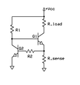
One style of current limiting circuit is shown in the image. The schematic represents a simple protection mechanism used in regulated DC supplies and class-AB power amplifiers.
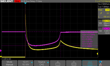
Q1 is the pass or output transistor. Rsens is the load current sensing device. Q2 is the protection transistor which turns on as soon as the voltage across Rsens becomes about 0.65 V. This voltage is determined by the value of Rsens and the load current through it (Iload). When Q2 turns on, it removes the base current from Q1, thereby reducing the collector current of Q1, which is nearly the load current. Thus, Rsens fixes the maximum current to a value given by 0.65/Rsens. For example, if Rsens = 0.33 Ω, the current is limited to about 2 A even if Rload becomes a short (and Vo becomes zero).
Further, this power dissipation will remain as long as the overload exists, which means that the devices must be capable of withstanding it for a substantial period. This power dissipation will be substantially less than if no current limiting circuit had been provided. In this technique, beyond the current limit, the output voltage will decrease to a value depending on the current limit and load resistance.

To reduce the heat that must be dissipated by the pass devices under a short-circuit, foldback current limiting is used, which reduces current in the short-circuit case. Under a short circuit, where the output voltage has reduced to zero, the current is typically limited to a small fraction of the maximum current.

The prime purpose of foldback current limiting in linear power supplies is to keep the output transistor within its safe power dissipation limit. A linear regulator dissipates the difference between input and output voltages as heat. Under overload conditions, the output voltage falls, so the difference becomes larger, thus increasing dissipation. Foldback helps to keep the output transistor within its safe operating area under fault and overload conditions. Foldback also significantly reduces the power dissipation in the load in fault conditions, which can reduce the risks of fire and heat damage.[1]
Many power supplies employ constant current limiting protection; foldback goes one step further by linearly reducing the output current limit as output voltage decreases. However, it adds complexity to the power supply. It can trigger "lockout" conditions with non-ohmic devices that draw a constant current independent of the supply voltage (such as op-amps). A foldback current limiter may also employ a transient delay to avoid lockout and limit localized heating at the short circuit.
A switched-mode power supply operating at the current limit with the output short-circuited does not have increased power dissipation in the power transistor(s), so foldback current limiting is an application feature only rather than one that also prevents a load fault from also destroying the power supply. The safety benefit of reducing the power delivered to a short circuit in the load is proportional to the operating current limit. Foldback current limiting is most likely to be found in a switch-mode power supply when it is a component in a product that is independently certified to meet regional safety standards.[2]
Single power-supply circuits
An issue with the previous circuit is that Q1 will not be saturated unless its base is biased about 0.5 volts above Vcc.
These circuits operate more efficiently from a single (Vcc) supply. In both circuits, R1 allows Q1 to turn on and pass voltage and current to the load. When the current through R_sense exceeds the design limit, Q2 turns on, which in turn begins to turn off Q1, thus limiting the load current. The optional component R2 protects Q2 in the event of a short-circuited load. When Vcc is at least a few volts, a MOSFET can be used for Q1 for lower dropout voltage. Due to its simplicity, this circuit is sometimes used as a current source for high-power LEDs.[3]
-
 Current limiter with NPN transistors (Vo output is located at similar location as PNP example)
 -
 Current limiter with PNP transistors


See also
References
- ^ Paul Horowitz, Winfield Hill, The Art of Electronics Second Edition, Cambridge University Press, 1989 ISBN 0-521-37095-7, p.316
- ^ Keith H. Billings (1999). Switchmode power supply handbook. McGraw-Hill Professional. p. 1.113. ISBN 978-0-07-006719-6.
- ^ "The New Stuff!!! Constant Current Source #1". Instructables. Retrieved 4 July 2012.
External links
- Current Limiting for Stepper Motors
- Current limiting resistor calculator for LED arrays
- Constant current & foldback current limiting
| Authority control databases: National |
|---|