
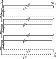
Counter-scanning (CS)[1][2][3] is a scanning method that allows correcting raster distortions caused by drift of the probe of scanning microscope relative to the measured surface. During counter-scanning two surface scans, viz., direct scan and counter scan are obtained (see Fig. 1). The counter scan starts in the point where the direct scan ends. This point is called the coincidence point (CP). With the counter scan, the probe movement along the raster line and the probe movement from one raster line to the other raster line are carried out along the directions that are opposite to the movements in the direct scan. The obtained pair of images is called counter-scanned images (CSIs).
YouTube Encyclopedic
-
1/3Views:1 054 64138 12467 325
-
TWL #9: The Secret Anti-Counterfeit Symbol
-
How To Connect To A Scanner In Access 2013
-
How to find poetic meter
Transcription
Principles
When the raster distortions are linear, i. e., when the drift velocity is constant, to correct drift, it is sufficient to measure coordinates of only one common feature in the direct and the counter scans. In case of nonlinear distortion, when the drift velocity varies during the scan, the number of common features on CSIs whose coordinates need to be measured increases in proportion to the degree of the nonlinearity.
Typically, the drift of the microscope probe relative to the measured surface consists of two components: one is associated with creep of the scanner piezoceramics, the other is caused by a thermal deformation of the instrument due to change in temperature. The first component is nonlinear (it can be approximated by logarithm), the second component can be considered as linear in most practical applications.
The use of the counter-scanning method allows, even in the case of a strong drift leading to errors in tens of percents, measuring the surface topography with error of few tenths of a percent.
-
 (a)
(a) -
 (b)
(b)


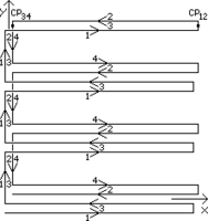
Fig. 1. Counter-scanning with (a) an idle line (shown by the dotted line), (b) no idle line. Digits 1…4 designate the numbers of the images obtained. 1, 3 are direct images, 2, 4 are counter images corresponding to the direct ones. CP is a coincidence point of the counter-scanned image pair. The raster presented conditionally consists of four lines.
Counter-scanned images
Counter-scanned images (CSI, CSIs)[1][2][3][4] are a pair of images obtained during counter-scanning. During the counter-scanning it is possible to obtain one or two pairs of CSIs (see Fig. 1). Each pair consists of a direct image and the image counter to it. First, a conventional image is obtained called the direct image, after that a counter image is obtained by reversing the movement direction along a raster line and the movement direction from line to line of the raster. The direct image of the second pair is formed by the retrace lines of the direct image of the first pair. The counter image of the second pair is formed by the retrace lines of the counter image of the first pair. CSIs are intended for correction of distortions caused by drift of the scanning microscope probe relative to the surface under investigation. To implement correction, it is sufficient to have at least one common feature between the direct and the counter images. As compared to a single CSI pair, the use of two pairs requires twice as much memory and processing time but on the other hand it allows increasing precision of correction and reducing noise level in the corrected image.
-
 (a)
(a) -
(b)
-
 (c)
(c) -
 (d)
(d) -
 (e)
(e)


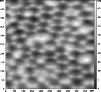
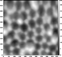
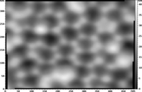
Fig. 1. Counter-scanned images of porous alumina (AFM, 128×128 pixels): (a) direct and (b) counter images of the first pair; (c) direct and (d) counter images of the second pair. Drift induced error makes 25%. (e) Corrected image, residual error makes 0.1%.
See also
References
- ^ a b R. V. Lapshin (2007). "Automatic drift elimination in probe microscope images based on techniques of counter-scanning and topography feature recognition" (PDF). Measurement Science and Technology. UK: IOP. 18 (3): 907–927. Bibcode:2007MeScT..18..907L. doi:10.1088/0957-0233/18/3/046. ISSN 0957-0233.
- ^ a b R. V. Lapshin (2011). "Feature-oriented scanning probe microscopy". In H. S. Nalwa (ed.). Encyclopedia of Nanoscience and Nanotechnology (PDF). Vol. 14. USA: American Scientific Publishers. pp. 105–115. ISBN 1-58883-163-9.
- ^ a b V. Y. Yurov, A. N. Klimov (1994). "Scanning tunneling microscope calibration and reconstruction of real image: Drift and slope elimination". Review of Scientific Instruments. USA: AIP. 65 (5): 1551–1557. Bibcode:1994RScI...65.1551Y. doi:10.1063/1.1144890. ISSN 0034-6748. Archived from the original (PDF) on 2012-07-13. Retrieved 2011-11-28.
- ^ J. T. Woodward, D. K. Schwartz (1998). "Removing drift from scanning probe microscope images of periodic samples". Journal of Vacuum Science and Technology B. USA: American Vacuum Society. 16 (1): 51–53. Bibcode:1998JVSTB..16...51W. doi:10.1116/1.589834. ISSN 0734-211X. Archived from the original (PDF) on 2012-07-10.
