

An antenna analyzer or in British aerial analyser (also known as a noise bridge, RX bridge, SWR analyzer, or RF analyzer) is a device used for measuring the input impedance of antenna systems in radio electronics applications.
In radio communications systems, including amateur radio, an antenna analyzer is a common tool used for fine tuning antenna and feedline performance, as well as troubleshooting them.[1]
Antenna bridges have long been used in the broadcast industry to tune antennas. A bridge is available which measures complex impedance while the transmitter is operating, practically a necessity when tuning multi-tower antenna systems.[2] In more recent times the direct-reading network analyzers have become more common.
YouTube Encyclopedic
-
1/1Views:51 739
-
Ham Radio MFJ-259B Antenna Analyzer Repair
Transcription
Types of analysers
There are several different instruments of varying complexity and accuracy for testing antennas and their feed lines. All can also be used to measure other electrical circuits and components (at least, in principle).[3]
- The simplest is an SWR meter, which only indicates the degree of mismatch; the actual mismatched impedance must be inferred by measuring several nearby frequencies and performing a few simple calculations. The SWR meter requires a transmitter or signal generator to provide a few watts power test signal.
- An antenna bridge is able to measure at low power, but also requires a supplied test signal; depending on the bridge circuit, it can be used to measure both reactance and resistance by reading values marked on knobs that have been adjusted for a match.
- The noise bridge and network analyzers both supply their own very low-power test signals; both are able to measure both resistance and reactance, either by calculation or by reading knobs adjusted for a match. Modern analyzers directly display resistance and reactance, with the calculations done internally by a microprocessor.
Antenna bridge
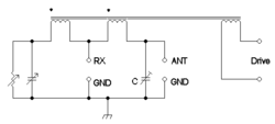
A bridge circuit has two legs which are frequency-dependent complex-valued impedances. One leg is a circuit in the analyzer with calibrated components whose combined impedance can be read on a scale. The other leg is the unknown – either an antenna or a reactive component.
To measure impedance, the bridge is adjusted, so that the two legs have the same impedance. When the two impedances are the same, the bridge is balanced. Using this circuit it is possible to either measure the impedance of the antenna connected between ANT and GND, or it is possible to adjust an antenna, until it has the same impedance as the network on the left side of the diagram below. The bridge can be driven either with white noise or a simple carrier (connected to drive). In the case of white noise the amplitude of the exciting signal can be very low and a radio receiver used as the detector. In the case where a simple carrier is used then depending on the level either a diode detector or a receiver can be used.[4] In both cases a null will indicate when the bridge is balanced.
Complex voltage and current meters
A second type of antenna analyzer measures the complex voltage across and current into the antenna. The operator then uses mathematical methods to calculate complex impedance, or reads it off a calibrated meter or a digital display. Professional instruments of this type are usually called network analyzers.[5]
Modern analyzers do not require the operator to adjust any R and X knobs as with the bridge-type analyzers. Many of these instruments have the ability to automatically sweep the frequency over a wide range and then plot the antenna characteristics on a graphical display. Doing this with a manually-operated bridge would be time-consuming, requiring one to change the frequency and adjust the knobs at each frequency for a match.
High and low power methods
Many transmitters include an SWR meter in the output circuits which works by measuring the reflected wave from the antenna back to the transmitter, which is minimal when the antenna is matched. Reflected power from a badly tuned antenna can present an improper load at the transmitter which can damage it. The SWR meter requires about 5–10 watts of outgoing signal from the radio to register the reflected power (if any), and then only indicates the relative degree of mismatch, not the reactive and resistive impedance seen at the end of the antenna's feedline.
A complex-impedance antenna analyzer typically only requires a few milliwatts of power be applied to the antenna, and typically provides its own signal, not requiring any test signal from a transmitter. Using a low-power test signal avoids damaging the analyzer when testing a badly-matched antenna.[5] In addition, because its signal power is very low, the analyzer can be used for frequencies outside of the transmit bands licensed to its operator, and thus measure antenna performance over an unrestricted range of frequencies.
See also
References
- ^ Wilson, Mark J.; Reed, Dana G., eds. (2007). The ARRL Handbook for Radio Communications. Newington, CT: The American Radio Relay League. ISBN 978-0-87259-976-5.
The comprehensive RF engineering reference
ISBN 978-0-87259-976-5 - ^ Battison, John. "Using the operating impedance bridge". Radio magazine (online ed.). New Bay Media. Archived from the original on 18 July 2016. Retrieved 20 July 2016.
The Radio Technology Leader
- ^ Hallas, Joel R. (W1ZR) (August 2016). "Antenna analyzers - the basics". QST Magazine. American Radio Relay League. pp. 32–34. ISSN 0033-4812.
{{cite magazine}}: CS1 maint: numeric names: authors list (link) - ^ Carr, Joseph J. (11 December 2000). "Chapter 17 Building and using an RF noise bridge". Secrets of RF Circuit Design (3rd ed.). McGraw-Hill / TAB Electronics. p. 319. ISBN 0-07-137067-6, ISBN 978-0071370677
- ^ a b Carr, Joseph J. (1 October 1999). "Chapter 5 Spectrum and network analyzers; Chapter 12 Antenna and transmission line measurements". Practical Radio Frequency Test and Measurement: A technician's handbook (1st ed.). Newnes. pp. 102, 319. ISBN 0-7506-7161-0, ISBN 978-0-7506-7161-3