


A schematic, or schematic diagram, is a designed representation of the elements of a system using abstract, graphic symbols rather than realistic pictures. A schematic usually omits all details that are not relevant to the key information the schematic is intended to convey, and may include oversimplified elements in order to make this essential meaning easier to grasp, as well as additional organization of the information.
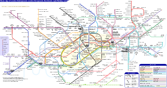
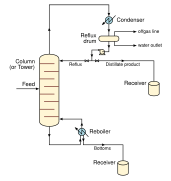
For example, a subway map intended for passengers may represent a subway station with a dot. The dot is not intended to resemble the actual station at all but aims to give the viewer information without unnecessary visual clutter. A schematic diagram of a chemical process uses symbols in place of detailed representations of the vessels, piping, valves, pumps, and other equipment that compose the system, thus emphasizing the functions of the individual elements and the interconnections among them and suppresses their physical details. In an electronic circuit diagram, the layout of the symbols may not look anything like the circuit as it appears in the physical world: instead of representing the way the circuit looks, the schematic aims to capture, on a more general level, the way it works. This may be contrasted with a wiring diagram, which preserves the spatial relationships between each of its components.
YouTube Encyclopedic
-
1/5Views:520 99835 714628 50821 2022 901
-
Understanding HVAC Schematics - 1
-
ESTech Schematic Diagram #Free Diagram #Complete Guide #How to Use #easy download #asiatelecom
-
First Time Using WYCKOFF Schematic l Forex Trading | Supply & Demand
-
Schematic Diagrams and Current Flow
Transcription
Types
Schematics and other types of diagrams, e.g.,
|


A semi-schematic diagram combines some of the abstraction of a purely schematic diagram with other elements displayed as realistically as possible, for various reasons. It is a compromise between a purely abstract diagram (e.g. the schematic of the Washington Metro) and an exclusively realistic representation (e.g. the corresponding aerial view of Washington).
-
 A semi-schematic map: Tabula Peutingeriana. While roads and features appear as abstract representations without resemblance to reality, their locations, orientations, and distances are as accurate as possible to make the map practical.
Electrical and electronic industry


In electrical and electronic industry, a schematic diagram is often used to describe the design of equipment. Schematic diagrams are often used for the maintenance and repair of electronic and electromechanical systems.[1] While schematics were traditionally drawn by hand, using standardized templates or pre-printed adhesive symbols, today electronic design automation software (EDA or "electrical CAD") is often used.
In electronic design automation, until the 1980s schematics were virtually the only formal representation for circuits. More recently, with the progress of computer technology, other representations were introduced and specialized computer languages were developed, since with the explosive growth of the complexity of electronic circuits, traditional schematics are becoming less practical. For example, hardware description languages are indispensable for modern digital circuit design.
Schematics for electronic circuits are prepared by designers using EDA (electronic design automation) tools called schematic capture tools or schematic entry tools. These tools go beyond simple drawing of devices and connections. Usually they are integrated into the whole design flow and linked to other EDA tools for verification and simulation of the circuit under design.
Programmable logic controllers (PLC) can be programmed using ladder diagrams.
In electric power systems design, a schematic drawing called a one-line diagram is frequently used to represent substations, distribution systems or even whole electrical power grids. These diagrams simplify and compress the details that would be repeated on each phase of a three-phase system, showing only one element instead of three. Electrical diagrams for switchgear often have common device functions designate by standard function numbers. Another type of diagram used for power systems is a three-line diagram.
For analysis purposes of a power system, from the one-line diagram, if the system is balanced, an equivalent per-phase (or single-phase) schematic diagram can be obtained. If all of the parameters are represented as impedances and voltage sources, the equivalent per-phase schematic diagram is called an impedance diagram. If all of the parameters are represented as admittances and current sources, the equivalent per-phase schematic diagram is called an admittance diagram.
If the power system is unbalanced, but it is linear (or can be approximated by a linear system), then Fortescue's theorem (symmetrical components) can be applied. In this way, from the one-line diagram, three different per-phase schematic diagrams are obtained, known as sequence diagrams: positive sequence diagram, negative sequence diagram, and zero sequence diagram. Each of these diagrams can be represented as an impedance diagram or as an admittance diagram.
Schematics in repair manuals
Schematic diagrams are used extensively in repair manuals to help users understand the interconnections of parts, and to provide graphical instruction to assist in dismantling and rebuilding mechanical assemblies. Many automotive and motorcycle repair manuals devote a significant number of pages to schematic diagrams.
See also
- Energy Systems Language
- Chart
- Diagram
- Logic gate § Symbols
- Straight-line diagram
- Topological map
- Transit map
- Open-source hardware
References
- ^ Thomas E. French, Charles J. Vierck (1975). Engineering Drawing and Graphic Technology, Eleventh Edition. McGraw Hill. ISBN 0-07-022157-X. pp. 621–624.