
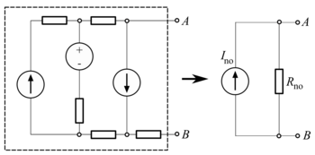

In direct-current circuit theory, Norton's theorem, also called the Mayer–Norton theorem, is a simplification that can be applied to networks made of linear time-invariant resistances, voltage sources, and current sources. At a pair of terminals of the network, it can be replaced by a current source and a single resistor in parallel.
For alternating current (AC) systems the theorem can be applied to reactive impedances as well as resistances.
The Norton equivalent circuit is used to represent any network of linear sources and impedances at a given frequency.
Norton's theorem and its dual, Thévenin's theorem, are widely used for circuit analysis simplification and to study circuit's initial-condition and steady-state response.
Norton's theorem was independently derived in 1926 by Siemens & Halske researcher Hans Ferdinand Mayer (1895–1980) and Bell Labs engineer Edward Lawry Norton (1898–1983).[1][2][3][4][5][6]
To find the equivalent, the Norton current Ino is calculated as the current flowing at the terminals into a short circuit (zero resistance between A and B). This is Ino. The Norton resistance Rno is found by calculating the output voltage produced with no resistance connected at the terminals; equivalently, this is the resistance between the terminals with all (independent) voltage sources short-circuited and independent current sources open-circuited. This is equivalent to calculating the Thevenin resistance.
When there are dependent sources, the more general method must be used. The voltage at the terminals is calculated for an injection of a 1 amp test current at the terminals. This voltage divided by the 1 A current is the Norton impedance Rno (in ohms). This method must be used if the circuit contains dependent sources, but it can be used in all cases even when there are no dependent sources.
YouTube Encyclopedic
-
1/3Views:16 681380 53172 680
-
Electrical Engineering: Ch 4: Circuit Theorems (24 of 35) Norton's Theorem Example 3
-
Norton's Theorem - by Dr. C. B. Bangal
-
Introduction to Norton's Theorem
Transcription
Example of a Norton equivalent circuit

- The original circuit
- Calculating the equivalent output current
- Calculating the equivalent resistance
- Design the Norton equivalent circuit
In the example, the total current Itotal is given by:

The current through the load is then, using the current divider rule:
![{\displaystyle {\begin{aligned}I_{\mathrm {no} }&={1\,\mathrm {k} \Omega +1\,\mathrm {k} \Omega \over 1\,\mathrm {k} \Omega +1\,\mathrm {k} \Omega +1\,\mathrm {k} \Omega }\cdot I_{\mathrm {total} }\\[5pt]&=2/3\cdot 5.625\,\mathrm {mA} =3.75\,\mathrm {mA} .\end{aligned}}}](https://wikimedia.org/api/rest_v1/media/math/render/svg/6401d8ddf361d0de7567c3581cf46d6937b14d9a)
And the equivalent resistance looking back into the circuit is:

So the equivalent circuit is a 3.75 mA current source in parallel with a 2 kΩ resistor.
Conversion to a Thévenin equivalent

A Norton equivalent circuit is related to the Thévenin equivalent by the equations:
![{\displaystyle {\begin{aligned}&R_{\rm {th}}=R_{\rm {no}}\\[8pt]&V_{\rm {th}}=I_{\rm {no}}R_{\rm {no}}\\[8pt]&{\frac {V_{\rm {th}}}{R_{\rm {th}}}}=I_{\rm {no}}\end{aligned}}}](https://wikimedia.org/api/rest_v1/media/math/render/svg/b5de3a14a1c09b01ae4a7941d18fc0f4f4230b08)
Queueing theory
The passive circuit equivalent of "Norton's theorem" in queuing theory is called the Chandy Herzog Woo theorem.[3][4][7] In a reversible queueing system, it is often possible to replace an uninteresting subset of queues by a single (FCFS or PS) queue with an appropriately chosen service rate.[8]
See also
- Ohm's law
- Millman's theorem
- Source transformation
- Superposition theorem
- Thévenin's theorem
- Maximum power transfer theorem
- Extra element theorem
References
- ^ Mayer, Hans Ferdinand (1926). "Ueber das Ersatzschema der Verstärkerröhre" [On equivalent circuits for electronic amplifiers]. Telegraphen- und Fernsprech-Technik (in German). 15: 335–337.
- ^ Norton, Edward Lawry (1926). "Design of finite networks for uniform frequency characteristic". Bell Laboratories. Technical Report TM26–0–1860.
{{cite journal}}: Cite journal requires|journal=(help) - ^ a b Johnson, Don H. (2003). "Origins of the equivalent circuit concept: the voltage-source equivalent" (PDF). Proceedings of the IEEE. 91 (4): 636–640. doi:10.1109/JPROC.2003.811716. hdl:1911/19968.
- ^ a b Johnson, Don H. (2003). "Origins of the equivalent circuit concept: the current-source equivalent" (PDF). Proceedings of the IEEE. 91 (5): 817–821. doi:10.1109/JPROC.2003.811795.
- ^ Brittain, James E. (March 1990). "Thevenin's theorem". IEEE Spectrum. 27 (3): 42. doi:10.1109/6.48845. S2CID 2279777. Retrieved 2013-02-01.
- ^ Dorf, Richard C.; Svoboda, James A. (2010). "Chapter 5: Circuit Theorems". Introduction to Electric Circuits (8th ed.). Hoboken, NJ, USA: John Wiley & Sons. pp. 162–207. ISBN 978-0-470-52157-1. Archived from the original on 2012-04-30. Retrieved 2018-12-08.
- ^ Gunther, Neil J. (2004). Analyzing Computer System Performance with Perl::PDQ (Online ed.). Berlin: Springer Science+Business Media. p. 281. ISBN 978-3-540-20865-5.
- ^ Chandy, Kanianthra Mani; Herzog, Ulrich; Woo, Lin S. (January 1975). "Parametric Analysis of Queuing Networks". IBM Journal of Research and Development. 19 (1): 36–42. doi:10.1147/rd.191.0036.
External links
 Media related to Norton's theorem at Wikimedia Commons
- Norton's theorem at allaboutcircuits.com