
| Part of a series on |
| Antennas |
|---|
 |
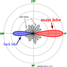
In a radio antennas, the main lobe or main beam is the region of the radiation pattern containing the highest power or exhibiting the greatest field strength.
The radiation pattern of most antennas shows a pattern of "lobes" at various directions, where the radiated signal strength reaches a local maximum, separated by "nulls", at which the radiation falls to zero. In a directional antenna in which the objective is to emit the radio waves in one direction, the lobe in that direction is designed to have higher field strength than the others, so on a graph of the radiation pattern it appears biggest; this is the main lobe. The other lobes are called "sidelobes", and usually represent unwanted radiation in undesired directions. The sidelobe in the opposite direction from the main lobe is called the "backlobe".
The radiation pattern referred to above is usually the horizontal radiation pattern, which is plotted as a function of azimuth about the antenna, although the vertical radiation pattern may also have a main lobe. The beamwidth of the antenna is the width of the main lobe, usually specified by the half power beam width (HPBW), the angle encompassed between the points on the side of the lobe where the power has fallen to half (-3 dB) of its maximum value.
The concepts of main lobe and sidelobes also apply to acoustics and optics, and are used to describe the radiation pattern of optical systems like telescopes, and acoustic transducers like microphones and loudspeakers.
YouTube Encyclopedic
-
1/3Views:2 0134 18432 805
-
Main Lobes In Antenna Systems
-
Radiation Pattern Lobes | Radiation Parameter of Antenna | Antenna and Wave Propagation
-
An introduction to Antenna Gain and Radiation Patterns
Transcription
See also
- Antenna boresight
- Antenna gain
- Beam radio navigation
- Beam waveguide antenna
- Beamwidth
- Side lobe
- Software defined antenna
![]() This article incorporates public domain material from Federal Standard 1037C. General Services Administration. Archived from the original on 2022-01-22. (in support of MIL-STD-188).
This article incorporates public domain material from Federal Standard 1037C. General Services Administration. Archived from the original on 2022-01-22. (in support of MIL-STD-188).
This electronics-related article is a stub. You can help Wikipedia by expanding it. |