

A digital potentiometer (also called a resistive digital-to-analog converter,[1] or informally a digipot) is a digitally-controlled electronic component that mimics the analog functions of a potentiometer. It is often used for trimming and scaling analog signals by microcontrollers.
YouTube Encyclopedic
-
1/3Views:22 5046192 573
-
في المختبر:: 167- ما هي المقاومة الرقمية (Digital Potentiometer) - (MCP4561 - X9C104)
-
Digital Potentiometer
-
Potenciometro Digital | Digital Potentiometer EDP2041
Transcription
Design
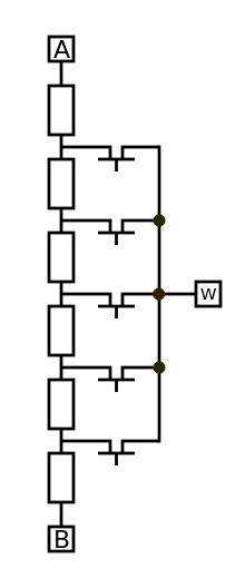
A digital potentiometer is built either from a resistor ladder integrated circuit or a digital-to-analog converter although a resistor ladder construction is the more common.[citation needed] Every step on the resistor ladder has its own switch which can connect this step to the output terminal of the potentiometer. The selected step on the ladder determines the resistance ratio of the digital potentiometer. The number of steps is normally indicated with a bit value e.g. 8 bits equals 256 steps; 8 bits is the most common, but resolutions between 5 and 10 bits (32 to 1024 steps) are available.[2] A digital potentiometer uses protocols like I²C or a Serial Peripheral Interface bus for signalling; some use simpler up/down protocols. Typical uses of digital potentiometers are in circuits requiring gain control of amplifiers (frequently instrumentation amplifiers), small-signal audio-balancing, and offset adjustment.
The resistor material is usually polysilicon or thin-film .[3]
Most digital potentiometers use only volatile memory, which means they forget their position when they are powered down (on power up they will report a default value, often their midpoint value) - when these are used, their last position may be stored by the microcontroller or FPGA to which they are interfaced. Some digipots do include their own non-volatile storage,[4] so their default reading on power up will be the same as they showed before they were powered down.[5]
Limitations
While quite similar to normal potentiometers, digital potentiometers are constrained by current limit in the range of tens of milliamperes. Also, most digital potentiometers limit the voltage range on the two input terminals (of the resistor) to the digital supply range (e.g. 0–5 VDC), so additional circuitry may be required to replace a conventional potentiometer, (although digital potentiometers with separate dual supply analog voltages are also available.)[6] Further, instead of the seemingly continuous control that can be obtained from a multiturn resistive potentiometer, digital potentiometers have discrete steps in resistance.
Another constraint is that special logic is often required to check for zero crossing of an analog AC signal to allow the resistance value to be changed without causing an audible click in the output for audio amplifiers. (Schematic needed)
Volatile digital potentiometers also differ from electro-mechanical ones in that on power up, the resistance will default to (possibly) a different value after a power cycle. Similarly, their resistance is only valid when the correct DC supply voltage is present. When voltage is removed, the resistance between the two end points and the (nominal) wiper are undefined. In an operational amplifier circuit, the off-state impedance of a real potentiometer can help stabilize the DC operating point of the circuit during the power-up stage. This may not be the case when a digital potentiometer is used.
Both electro-mechanical and digital potentiometers generally have poor tolerances (typically ±20%),[7] poor temperature coefficients[8] (up to many hundreds of ppm per degree C),[8] and a stop resistance that is typically about 0.5-1% of the full scale resistance. Note that stop resistance is the residual resistance when the terminal to wiper resistance is set to the minimum value.[citation needed]
With a digital potentiometer, the resistance might be depended on supply voltage.[7]
Digital potentiometer have a limited band width due to parasitic capacitance in device. Parts with lower End-To-End resistance typically have a greater band width.
The transmission gate/switching element in the Digital potentiometer cause harmonic distortions.
A multiplying DAC used as a digital potentiometer can eliminate most of these limitations.[9] Typically a signal span of +15V to -15V is possible, with 16 bit control, i.e. 65535 discrete set points, and drift and non-linearity are negligible. However a DAC has to be initialised each time the system is powered on, which is typically done by software in an embedded microcontroller. A multiplying DAC can not be directly used as a rheostat (2 wire connection), but in that mode a digipot performs badly anyway, due to its temperature coefficient and resistance tolerance.[citation needed]
Applications
- LCD-Contrast/Brightness
- Sensor Calibration
- Digital Volume Control
- Programmable Comperators
- Programmable Low/High Pass Filters
Alternatives
See also
References
- ^ "Digital potentiometers - frequently asked questions". Analog Devices. Archived from the original on 2011-09-07.
- ^ "Digital Potentiometer Family Selection Guide". AD5207 - 2-channel 256-position digital potentiometer - datasheet (PDF) (Technical report). Analog Devices.
- ^ "Digital Potentiometers - Where and How to Use - Education". Analog Devices. 3 October 2014. Retrieved 14 May 2023.
- ^ "DS1855 Dual Nonvolatile Digital Potentiometer and Secure Memory". Analog Devices. 5 October 2001. Retrieved 14 May 2023.
- ^ "Dual Nonvolatile Digital Potentiometer and Secure Memory" (PDF). analog.com. Retrieved 14 May 2023.
- ^ "7/8-Bit Single, +36V (±18V) Digital POT with SPI Serial Interface and Volatile Memory" (PDF). Microchip. Retrieved 14 May 2023.
- ^ a b "Understanding Digital Potentiometer Resistor Variations" (PDF). Microchip. Retrieved 14 May 2023.
- ^ a b "DS1845/DS1855 Temperature Coefficient Analysis". Analog Devices. 7 June 2002. Retrieved 14 May 2023.
- ^ "Multiplying DAC makes programmable resistor". EDN. 24 June 1999. Retrieved 14 May 2023.
External links
- Digital potentiometer - the Resistor Guide
- Designing with Intersil Digitally Controlled Potentiometers (XDCPs)